Samus' Arm Cannon
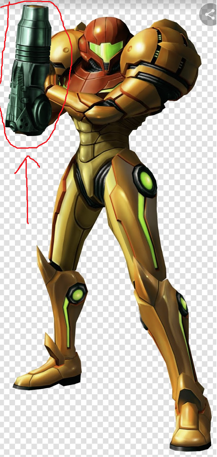
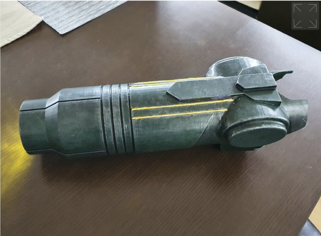
This all started from a silly lunch conversation at work where we ended up brainstorming what one could reasonably fit into an arm-cannon-sized prop that would be useful other than fighting aliens - I’d suggested a fold-out broom and vacuum (roombas can be quite compact; why not this?), someone else said a windex spray cannister, someone said a flamethrower … and then I found a really well made complete model online and thought … yeah, I could actually make this:
I decided to start with adding a Nerf gun as the main feature before anything else fancy, and then later decided not to add anything else or do other versions as these were really hard to make. The vacuum cleaner-combined-broom-combined-windex would be fun though.
Contents
Materials
Given that I’d found the model on Thingiverse I was always going to 3D print the main structure of the cannon, and I typically use PLA; the question remained for what to do about all the other parts. I had originally thought to use a Raspberry Pi for the brains; this would let me have a nice touch screen interface in the cannon for controlling things like nerf gun power, lights, reading battery levels, etc - this turned out to not work (read on in Modelling and printing and Electronics sections).
I bought a NERF Rival Charger MXX-1200 nerf gun to use inside, and there was one reason with two main advantages behind it for this choice.
- Firstly, it was a flywheel ball-based nerf gun. Normally nerf guns fire small foam darts, using either a spring or a blast of compressed air. A spring mechanism would have required the spring to sit behind the point of firing, adding an extra six inches or so onto the length already needed. Compressed air could have been piped from further down my arm, but would have needed either cannisters or some mechanical motion to recompress the air, which I expected to be difficult. Then there’s the darts - normally these are stored vertically in a clip:
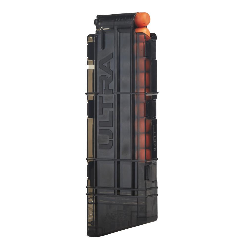
and this would not fit easily into the arm cannon. I could stack them end-to-end, but they’d then need to be shifted sideways at some point.
The flywheel Nerf Gun used these little foam balls, about two and a half centimetres diameter,

which meant that I could store them in a pipe running down the length of the cannon next to my arm, and that they could then roll into the firing point easily - no need to stack one direction, and then move in a different direction. This would be much easier to design.
- Secondly, take a closer look at the flywheel:
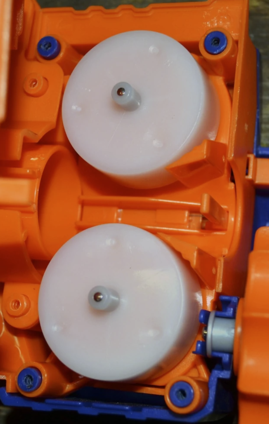
This propels the balls by having the trigger activate the flywheels, spinning them up to speed, and then pushing the ready ball far enough into the wheels that they catch it and fling it out. As this resets the next ball can roll forward up until a point, where it would need to be pushed to go further. This is much more compact than a spring, and all I would need to do is mount it in front of my fist in the cannon and allow the balls to roll into it (or so was my thinking).
The last material consideration was lights - I wanted LEDs in this, as the arm cannon glows in the games
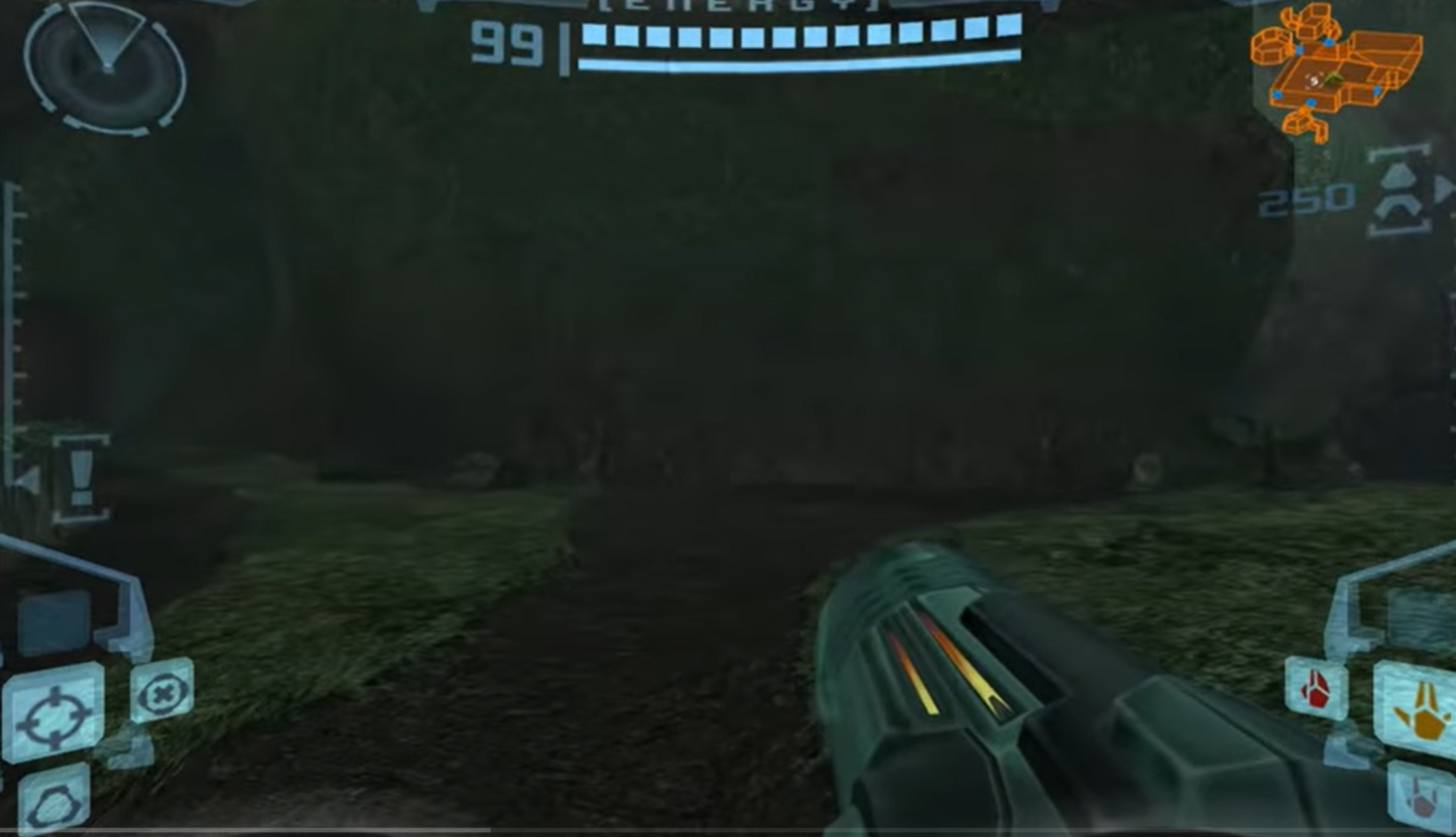
and has particular effects when charging, firing, etc. From the games I could see that it’s typically an orange glow, pulsing along those inset channels. The model I used had these channels, so I thought to mount LEDs on the inside of the cannon and the sparse structure of the 3D print should allow enough light through whilst also dispersing it from being points to being a general smudge. Neopixels were the easiest route - these are technically just WS2812 LEDs on a flexible copper backing, but with considerable software support for raspberry pi and arduino.
All the pieces seemed in place to me, so time to start modelling.
Modelling and printing
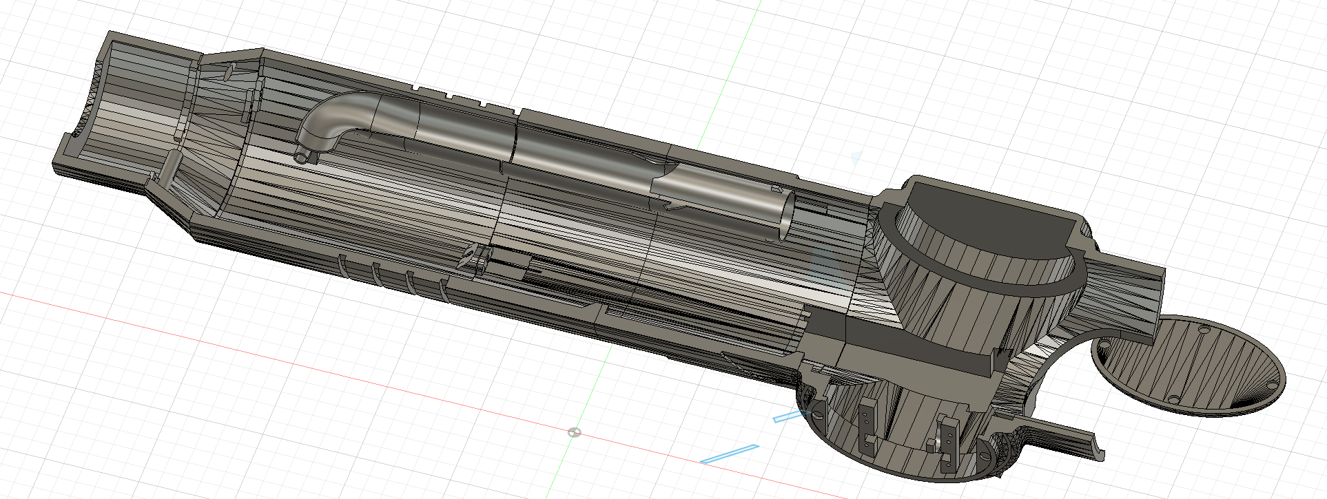
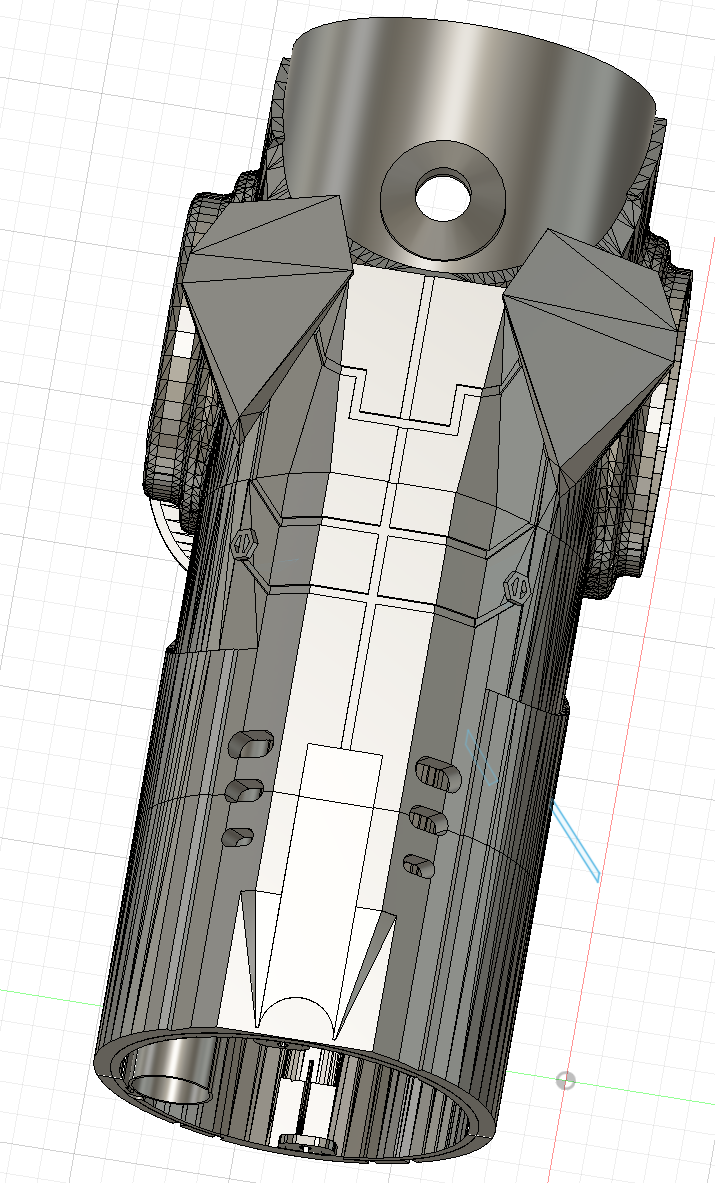
I started to model this in Tinkercad, which, while it’s a great program, was an outright mistake. It does not give me the fine-grained control I need for a model this complicated. So I soon moved to Fusion360, an absolute beast of a program that I still barely understand, but could do considerably more in. This allowed me to easily slice the model into its different sections: the front piece, the cone, three sections of tube, and the elbow piece:
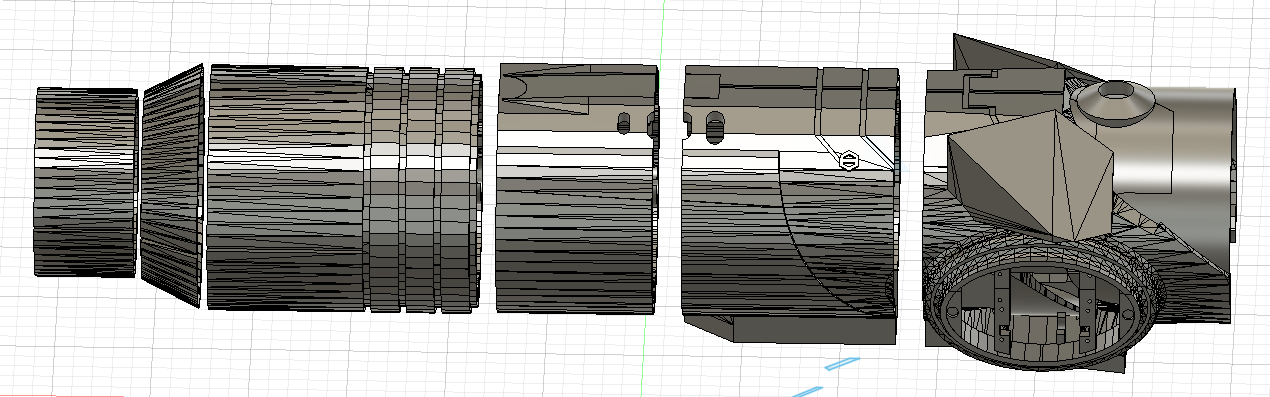
This would make both printing and prototyping easier - smaller prints, quicker turnaround, and fewer wasted prints. As I modelled other parts I added screw-based joins between these pieces so they could easily come apart if needed.
First thing to sort out was sizing - the arm cannon comes up to Samus’ right elbow, so this needs to fit my entire right forearm and hand, and then also have room for the nerf gun at the front. I measured my arm length with my hand in a fist (I had always imagined that there would be a crossbar I would hold to keep the cannon on, and have controls on), the length of the nerf gun flywheel piece, added a couple of ball-diameters to account for room for the barrel coming in and a firing mechanism, and then decided that this should all fit in the main tube - the cone and smaller tube at the front would just be for lighting and the balls flying through on their way out. The middle tube piece was also the easiest piece to stretch without stretching any existing detail beyond recognition. Next in sizing was diameter - again, this has to fit my forearm and the nerf gun, so it needs to be wide enough. I went to Home Depot’s PVC pipe section and stuck my arm in different PVC pipes to see how tight various diameters fit, how much motion I had, how much a closed fist rubbed against the sides, and so on. 4” was an almost perfect fit on my arm, so I scaled the model up to that and started some test prints. If you intend to make a similar model, I recommend this method of finding out the right size for you.
The nerf gun
The hardest thing to fit was always going to be the nerf gun flywheel, and I wasn’t sure how best to do this, so I printed a test cone piece and sat around measuring and modelling:
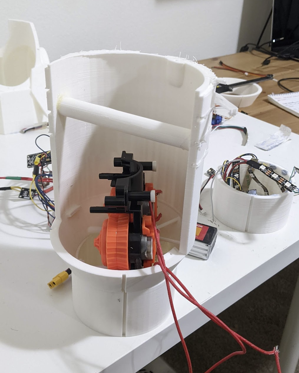
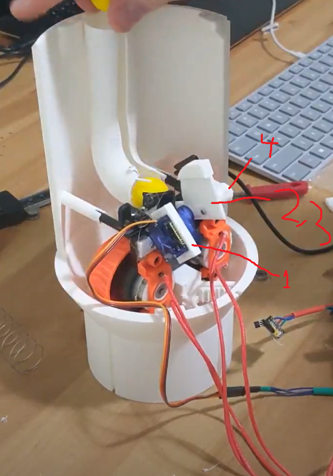
Perhaps I should have modelled the actual flywheel, but at this stage that was possibly beyond my skill? I worried I wouldn’t do it accurately, and that this would propagate more errors through the whole build. It ended up being a really tight fit - I could not have made the cannon any narrower - but with some grinding down of plastic edges I fit the flywheel jutting up into the cone, which would leave a decent amount of room for a firing mechanism between this and my hand. To hold it in place I created supports to match the existing flywheel supports and hold them, as well as a back support piece to hold it from the other side. This went through several iterations as I got the mounts dialed to a sweet spot of supporting whilst also allowing me to take the flywheel in and out and join the cone to the front piece. Here’s the final design:
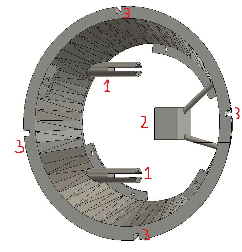
The slots labelled ‘1’ held the rods coming off my flywheel in the same way the real nerf gun had, and the box labelled ‘2’ supported the flywheel from behind. Combined with similar rods to ‘1’ but further back along the cannon, these pieces all made sure the flywheel wouldn’t move anywhere while firing. With this properly supported, I moved on to start modelling a barrel to lead into the flywheel and the firing mechanism. Some consideration went into the relative rotation of the flywheel to the cannon tube, since the cannon tube had the inset channels (lablled ‘3’) and I wanted to stick LEDs on the inside to shine through those. To achieve this I had to make sure that the flywheel supports did not get in the way of where I wanted LEDs. This worked well, until I actually tried to fit the LEDs in there and realised they sat just below the actual wheels - and by just I mean the wheels scraped them until I got in there with a file and filed the wheel edges down. I probably could have planned that better, or alternatively just modelled a trench for the LEDs to sit in opposite the inset channels. The tube shell was getting very thin already, and … I thought of this idea too late. Ah well. I’ll further discuss the final LED mounting later. Back to the cannon.
Once I was working on adding the barrel for the nerf balls in and the supports for the flywheel onto the first part of the tube, I had to decide the relative rotation of the cone to the main tube. The reason for this is my arm had to fit down there, and my elbow locked the elbow piece into place, so the entire cannon couldn’t rotate relative to my arm. The back half of the cannon tube had exterior designs that carried across multiple pieces, so it had a locked rotation too, relative to the final elbow piece. The front half of the tube did not, but I did want an inset channel aligned with the screen that would eventually sit atop the elbow piece. And given the shape of my arm, the barrel had to fit down the underside of my wrist, and curve up towards my hand, or on top of the wrist and curve over the fist down into the flywheel. I eventually settled on under the wrist, and modelled a cylinder a bit bigger than a nerf ball that ran down the tube and curved into the feeder point on the flywheel:
I reasoned that any crossbar for my hand to hold and press buttons on could a) be added later, and b) would only get in the way for now, so it was excluded from the design - what you see in the phot above is glued in to test. Then came the question of how to push the balls from the feeder point into the flywheel, and at the same time prevent them from accidentally going in there. A servo sounded like a good idea, one of those super light micro servos (https://www.adafruit.com/product/169) that can practically be powered from an arduino. I needed a few things:
- a mount for the servo on the flywheel piece
- a rotating servo arm that would stop a ball going through with gravity, but push a ball through when wanted
- this arm also needed to not let the next ball through until after it had pushed the first and reset
- after some experiments, this also needed a support for the arm so it couldn’t come off the servo.
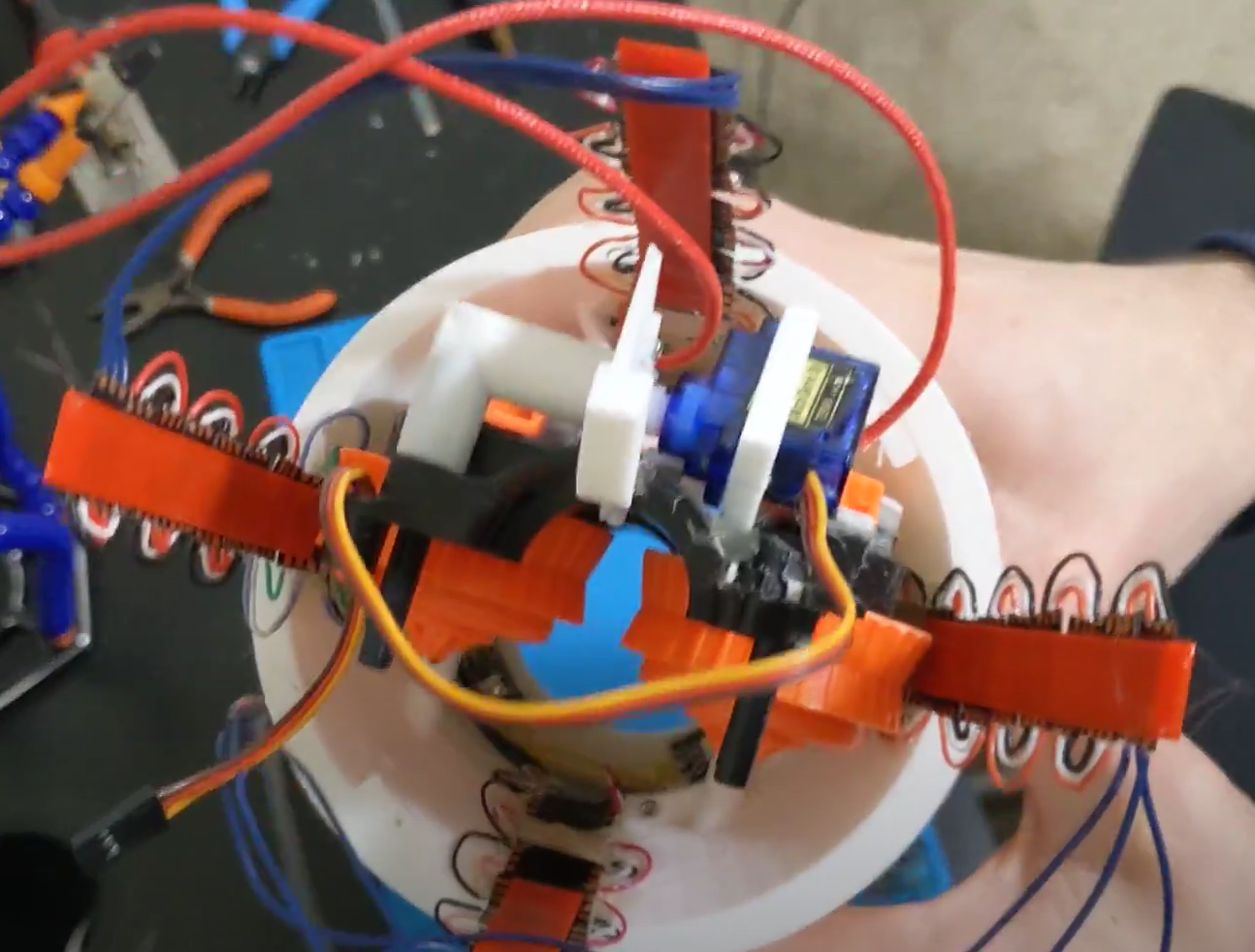
Let’s go over my design. Here’s all the components:
The support had to be designed in conjunction with the arm, as the arm length affected where the servo would sit. I sliced a slit with a dremel and hacksaw down the middle of the flywheel piece to accomodate a rotating arm from the servo, and made it thicker and longer than necessary - the ball would still easily be supported. The main part of the support was a brace around the servo, and what remained was any extension required to precisely place it, so I came back to this after designing the servo arm. I went through a few different designs for the servo arm on paper,
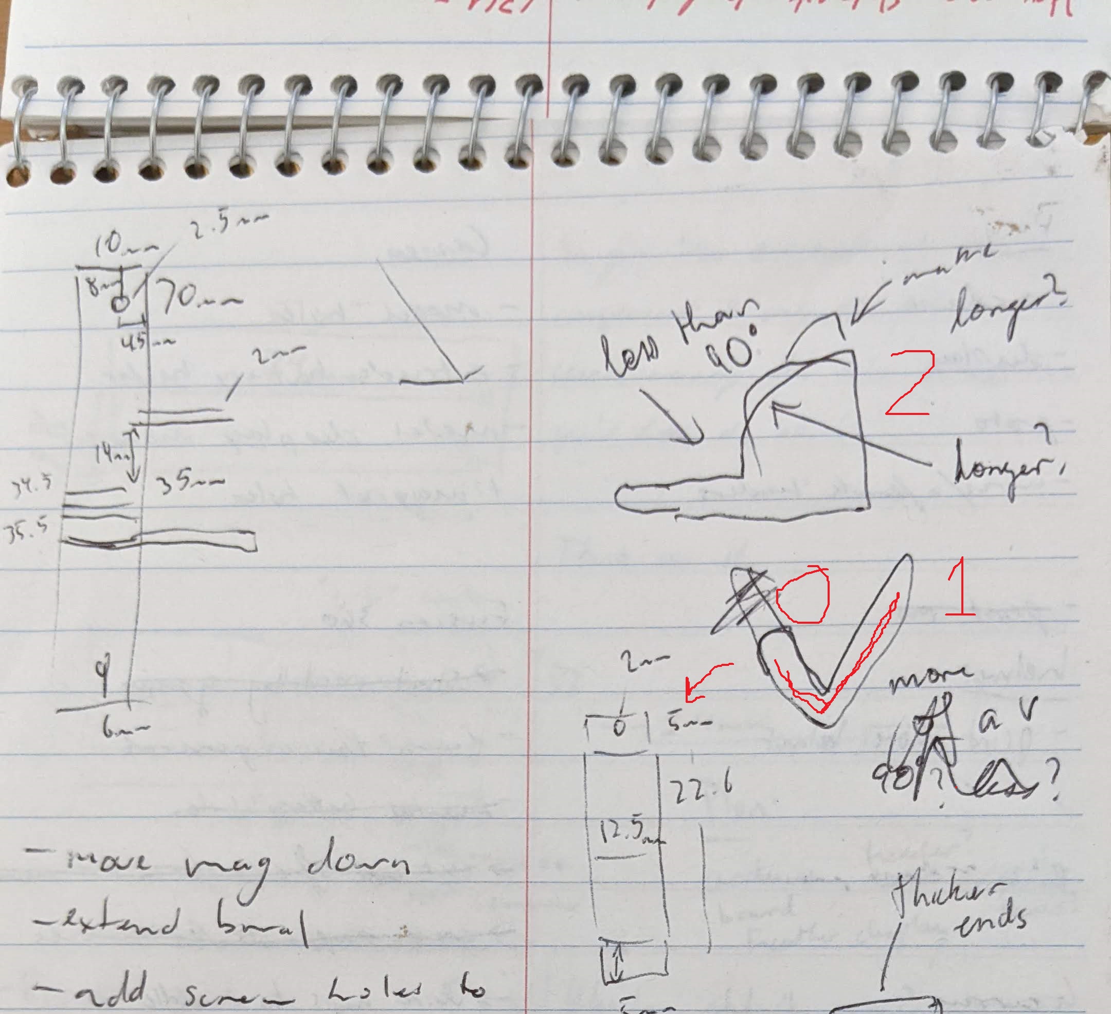
before settling on what can be seen in the numbered photo above. I started with a basic L shape (or perhaps V shape?), leblled ‘1’ above - the little arm of the L would sit between the ball and flywheels in the default position, and prevent accidental firing. The ball itself would not be able to move to the sides from the given flywheel barrel shape, and the long arm of the L would stop it from moving backwards. By having the barrel end a hair more than a ball diameter away from the feeder point, this prevented more than one ball at a time in the feeder. So far so good. Then for firing, the servo would rotate this forward (see red arrow) - the little arm drops out of the way into the slot I cut, and the long arm of the L comes forward to push the ball into the flywheels. Two problems:
- what’s stopping the ball from being pushed up out of the flywheel track completely?
- what’s stopping the next ball from falling into the feeder and back towards my arm while the current ball is being pushed into the flywheel?
I redesigned the arm and the barrel to fix both these problems: the barrel got a little extended roof that would stretch over toward the flywheels, to keep any ball in the track, and the arm got a curved back (see ‘2’, above ‘1’). This would hold any balls in the barrel at bay as it curved forward, only letting one drop when fully back. I created a servo mount that accomodated this, gave it a test, and it worked! A bit. The end part needed to be thicker, otherwise it would attempt to push the ball and just bend to one side due to the plastic being weak. The other thing that happened was the arm would occasionally come off the servo. So I made the arm thicker, and designed a support to sit on the other side of the arm, mounted via bearing to the flywheel base. This worked, and now I could get on with the rest of the barrel. The rest of the barrel was mostly just length, to hold as many as I could - in fact, I probably could have and should have extended it further than I did, but I didn’t want it to cross another print boundary - it was already crossing one, and each interface was potential for trouble. Such worries were never realised, but I wanted to keep this simple. I stopped the barrel just before the elbow section of the gun, and designed a cap that would fit on the end and hold itself in with some notches on the side. This way, if I needed to replace the spring, or work on any other parts, I could remove the entire spring piece by just popping off the end cap. This held the spring in, but not well - a small jostle could make it pop off vertically, and have the spring shoot out. I tried designing thicker caps, or ones that held around the circular shape as well as were notched, but since these were SLA-printed, they were very brittle. Any designs that were FDM-printed though either didn’t have the detail, or were similarly brittle due to the FDM layers. So I kept an SLA-cap and just glued it in with hot glue, since this can be pulled off:
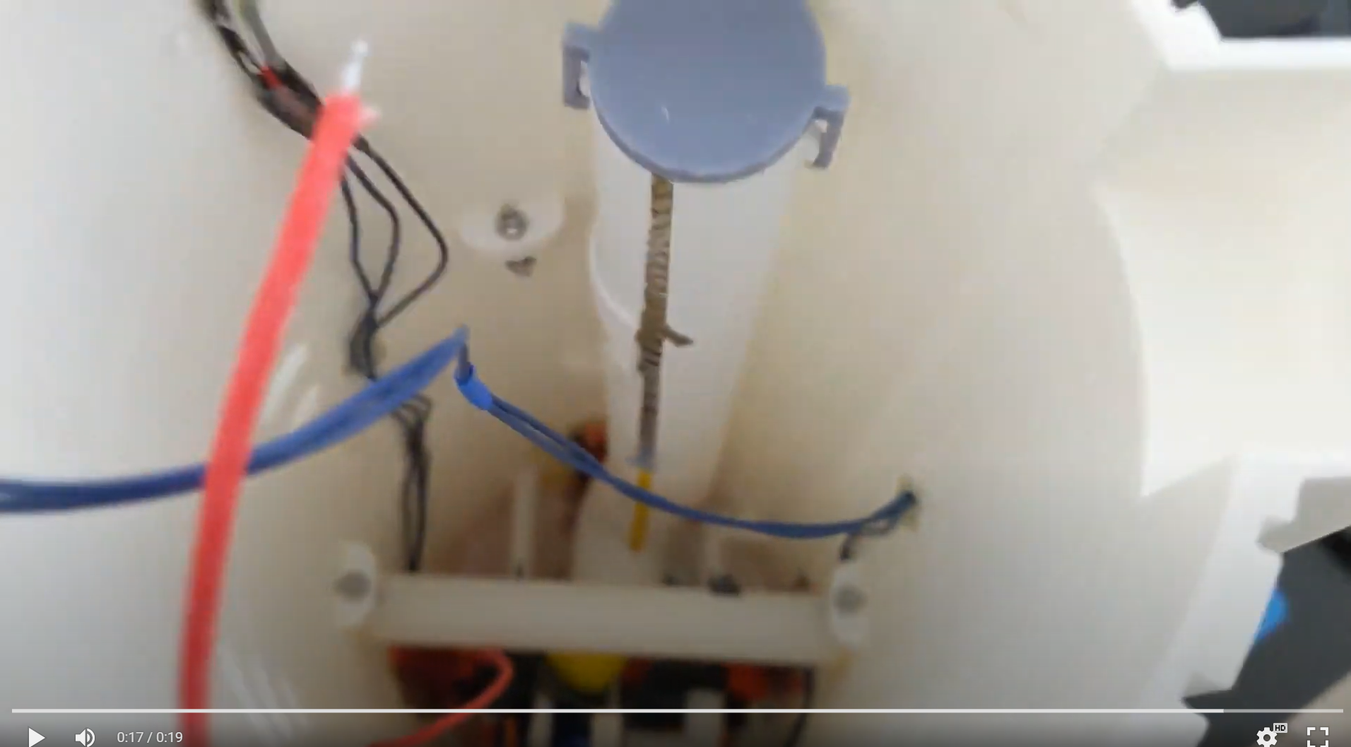
The barrel also needed to be reloadable in a way that didn’t involve getting the spring out, as the spring was a nightmare to put back in. I designed a hole in one side near the end, and a notch. This notch would hold what I called the ‘spring train’ - a flat circle that attached to the front of the spring, to press against the balls. So that I could pull it back and lock it into the notch, I added a T-shape to the top of this circle, that would poke up through the slot that ran the length of the barrel. With this, I could control where the spring was with my hand, pull it back to the notch, or whatever else.
It’s difficult to show this on the proper gun, and I don’t have a spare spring, but I got come rough video of what reloading looks like. It’s slow and awkward, but I can reload - an easy way to store the balls I’ve fired at a halloween party, for example.
To summarise, here’s the cross section of the entire gun:
That was all the modelling required to have the basics of the nerf gun - there’s more to fit any electronics required, but that’s the next section.
Circuit board mounts and access
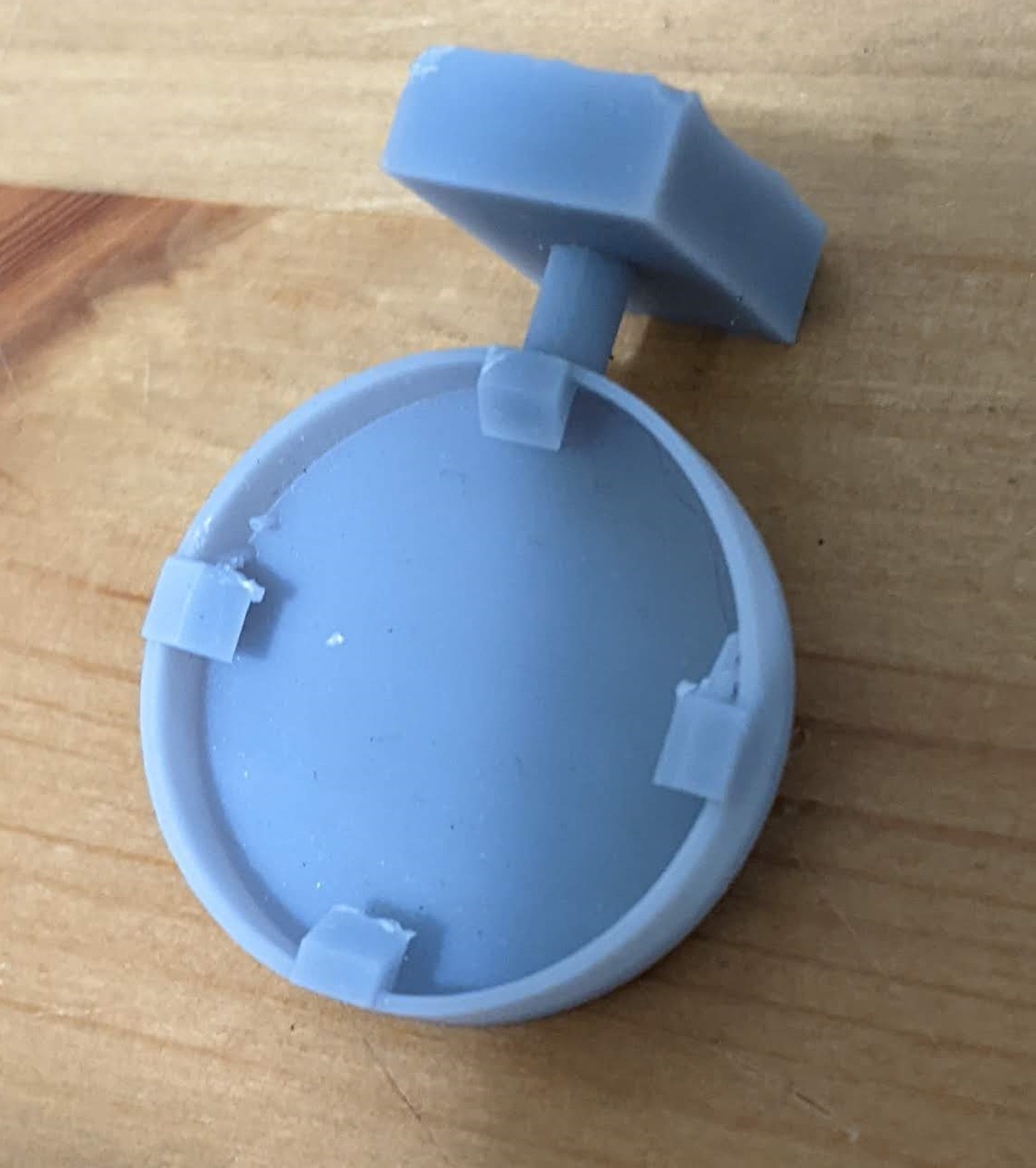
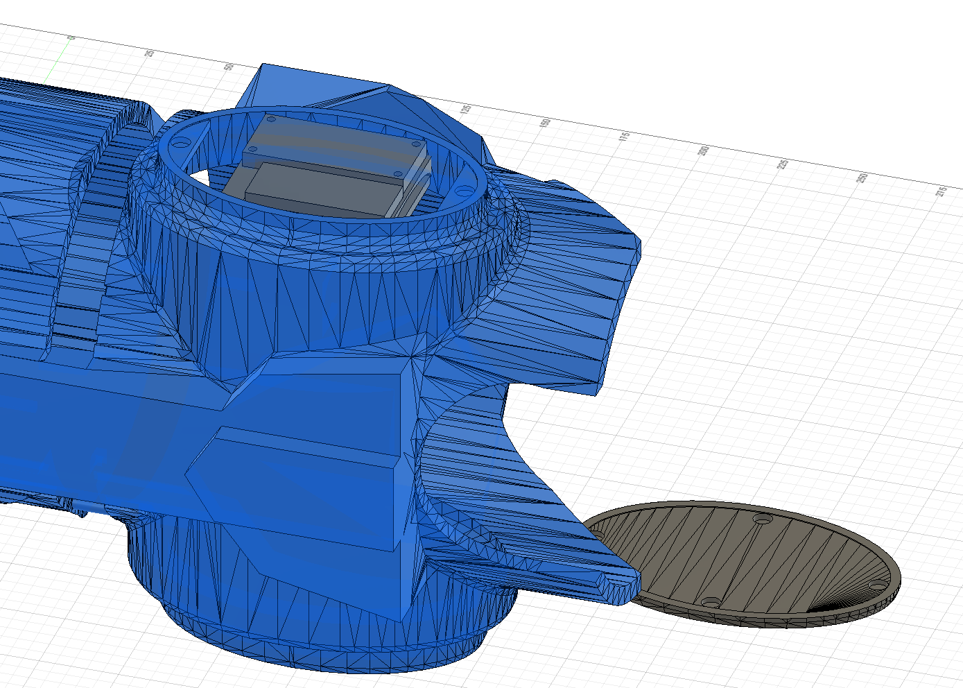
I’d always envisioned having a panel I could remove to access a display and some control buttons - after all, I might want to deactivate the nerf gun, so that no one could fire it as I passed it around, or lower LED brightness, or even control nerf gun power. Or maybe even just visualise live data about the gun - battery voltage, nerf balls remaining, etc. Samus’ gun never has a screen on it, in any of the games, so this had to be hideable - hence a removable panel. I opted for one of the elliptical panels that sat either side, choosing the one that meant I would twist my arm toward me (this felt more comfortable):
This was easy to slice off in CAD about half a millimetre before the internal ceiling of the gun, so that the sliced-off piece had a raised bevel. To hold the piece on, but allow it to be removed, I bought some small circular magnets and made holes for these - these would just be friction-fitted in. The holes that actually printed in the test version were too small, which meant I had to slowly dremel them out to make the big enough for the magnets. On the bright side, this meant that I could made the holes just as big as needed, and no bigger - an excellent friction fit.
So now I have access to where I want to have a display, and a bit of a cubby hole in which to store some of the electronics - the ellipse on the other side can hold some more. Let’s take stock of what I need:
- a display that fits within this ellipse
- some sort of programmable chip board with IO pins
- a battery
- a motor driver
- LEDs
- buttons
That’s actually quite a lot. At first I wanted a Raspberry Pi, but the original raspberry pi size - about a credit card in surface area - was too big to fit in the ellipse. Hmm. What about a smaller Raspberry pi - the Raspberry Pi Zero? No, that was out of stock everywhere …. what else …
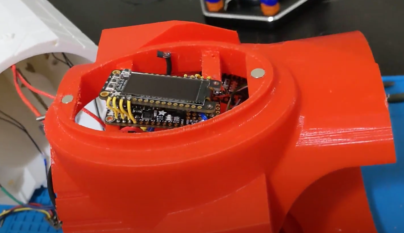
I spent some time thinking and came across some very slim arduinos on Adafruit.com: the Feather series - and these came with displays the same size, that included three buttons! Perfect! The datasheets also have the circuit board dimensions and the spacing between the screw holes in the circuit board, so I modelled some rails across the ellipse to hold the board.
Alright, we’ve mounted display and microchip. What next? I need to be able to detect whether the panel has been removed. Hall effect sensors detect the presence or absence of a magnetic field, and I already knew I could mount little magnets int eh panel lid - another magnet hole was mounted, and you can read the rest of the magnetic field detection story in the Electronics section.
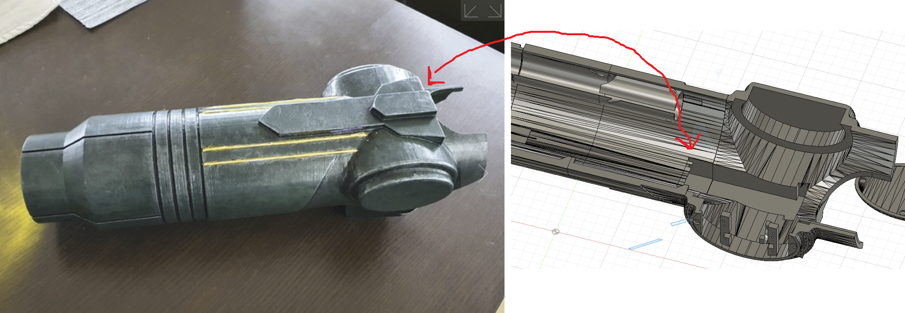
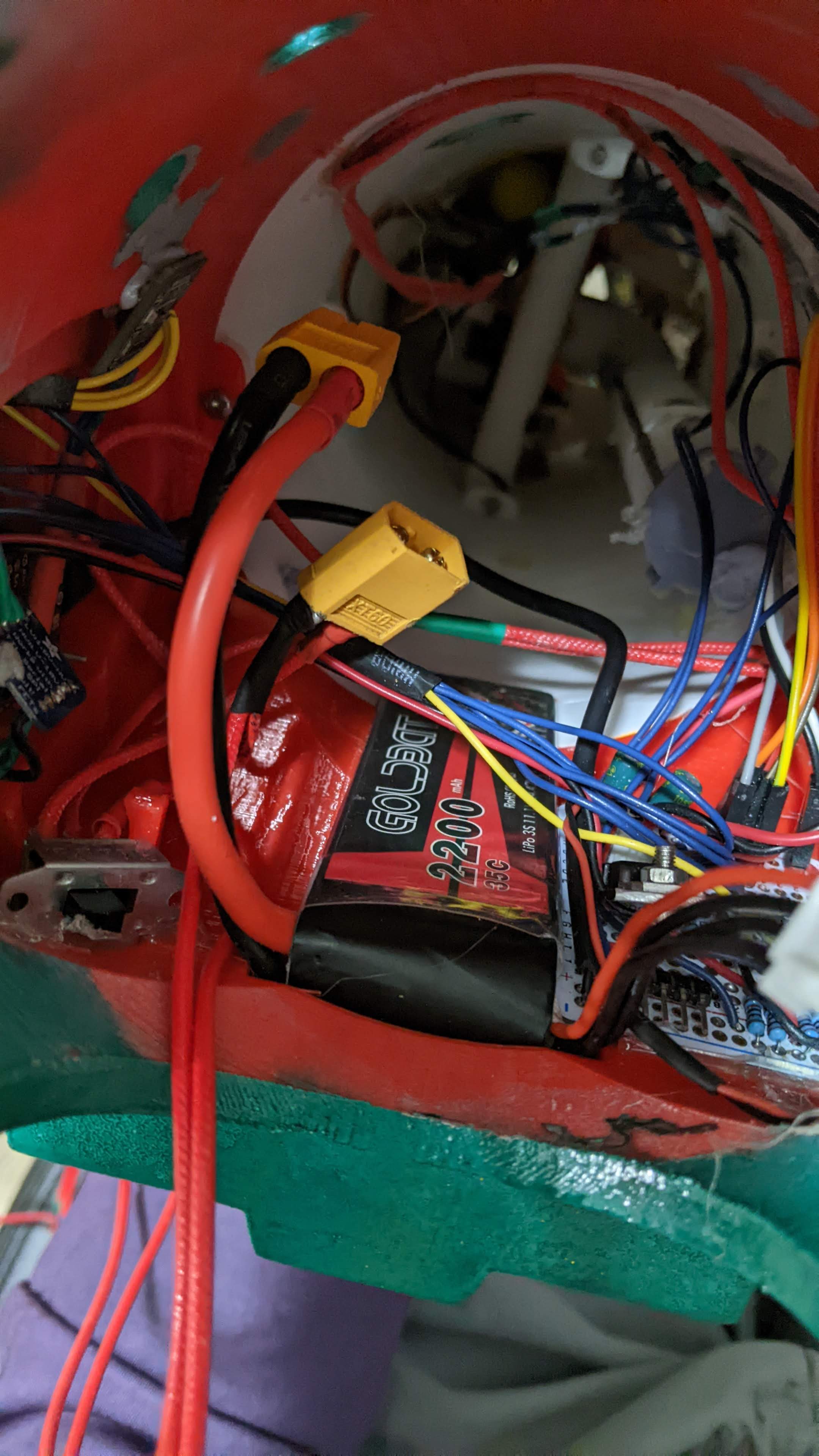
Next, a battery. I wanted to use 12v for the motors, since the nerf gun was originally powered by 9v and 12v was close enough and would give me good power - this was also easy to achieve with a 3S LiPo battery, and I had a LiPo charging setup. Perfect! This was my chosen battery: a 3 cell 2200maH LiPo - this would deliver 12v and all the amperage I would need for lights and the occasional motor spin-up. Looking for a good spot on the gun to mount it, I decided the arrow shape in the side near the elbow would work, pointed out here on both inside and outside with the red arrow:
But as it stood, it wasn’t protruding enough. Turns out the battery would have fit regardless, as this ended up being roomy, but I don’t regret the decision to expand - roomier is easier than tight. I extruded the whole shape so that the battery could fit entirely within it, and then extended it down the arm towards the tip more. This meant it crossed the boundary to the next piece, but that was ok - nothing mechanical happening here, just squishing a battery in. I wanted a snug fit, so the battery wouldn’t move, so I made it just big enough - LiPo pouches have some squish to them, and this worked out:
For the LEDs, I considered modelling some little square slots to fit the square LEDs of the strip, so that these would be flush with the inside of the barrel … but that’s a lot of effect. So nothing was modelled for the LEDs. They can just be glued down.
Finally, a motor driver. I used a h-bridge-based motor driver for arduino, which … just fit almost perfectly into the opposite ellipsoid, straight off the bat! I did have to remove the heatsink for this. Hmm … do I really need all that heatsink? This board was taking in raw 12v from the LiPo, and pumping an amount proportional to my PWM signal into the motors. These motors were spinning up whenever I chose to fire, and then going back to zero. Assuming I fired rarely, and seeing that the datasheet for this driver allowed for (checks notes) 40 amps to go through … yeah I think I can remove most of the heatsink. I cut the blades off to make it flat, and just glued the motor driver down, no modelling needed. Perfect.
For the rest fo the Electronics discussion, skip to the next section (some of this is repeated). For the final modelling, keep reading.
Fitting my arm
I’ve already discussed needed to lock in a relative rotation of my arm to the cannon, and the other thing I needed to make sure of was that this entire package was long enough - from cone to elbow end, I needed to fit the nerf gun flywheels and my fist to elbow, without this being too long. Too short wasn’t great, but also didn’t ruin the entire look. I measured the length of the flywheel piece, the length of my arm, added some estra, and then extended the middle bit.
Extra detail
Finally, the greeblies - the little bits of extra detail that strictly and functionally are not necessary, but really are the icing on the cake. You don’t notice when they are there, but you tend to notice when they are not. I was working from this model of the cannon:
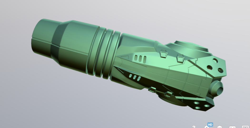
and comparing to my model, it has more underside detail.
I defintiely did and do not have the skill to model a lot of that, but I can attempt to approximate it. I ended up going for:
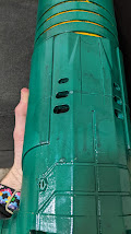
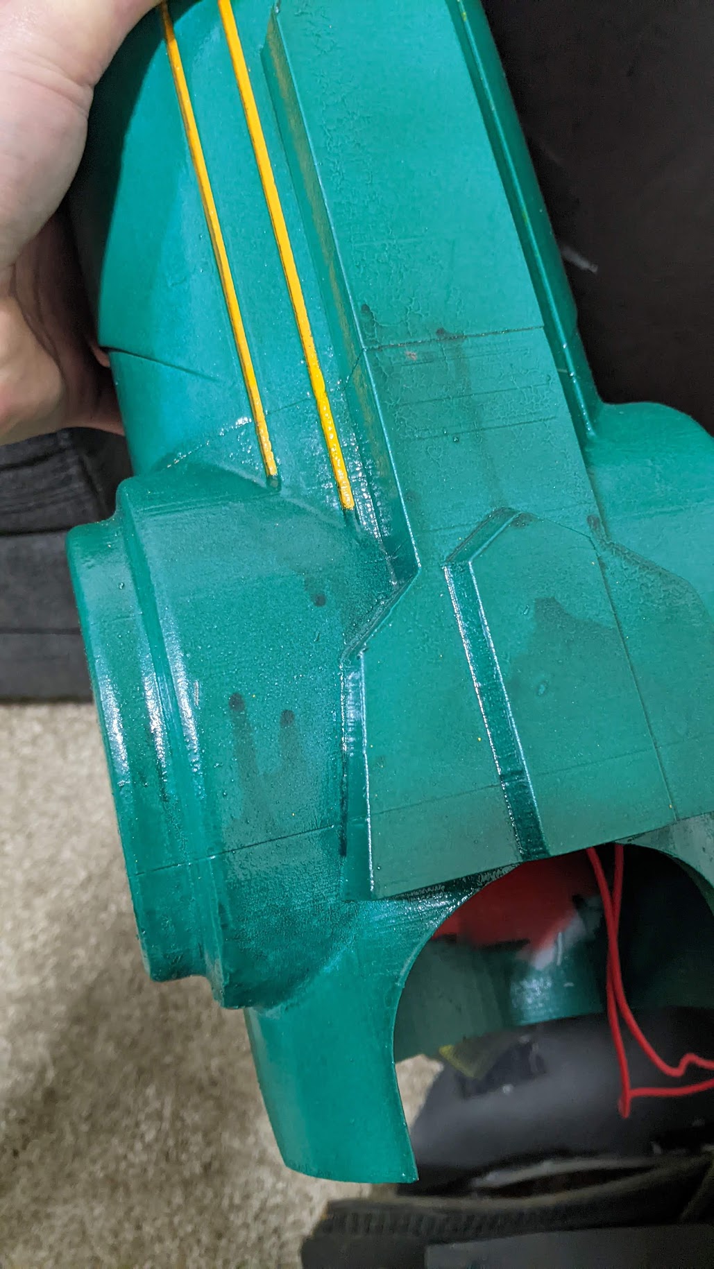
- those thin shallow grooves
- the elliptical holes in the sides (air vents?)
- the raised hexagons
- the circular knob at the end
- the holes in the triangular flares
I could talk about the modelling process, but … I just modelled them. Here’s what I did:
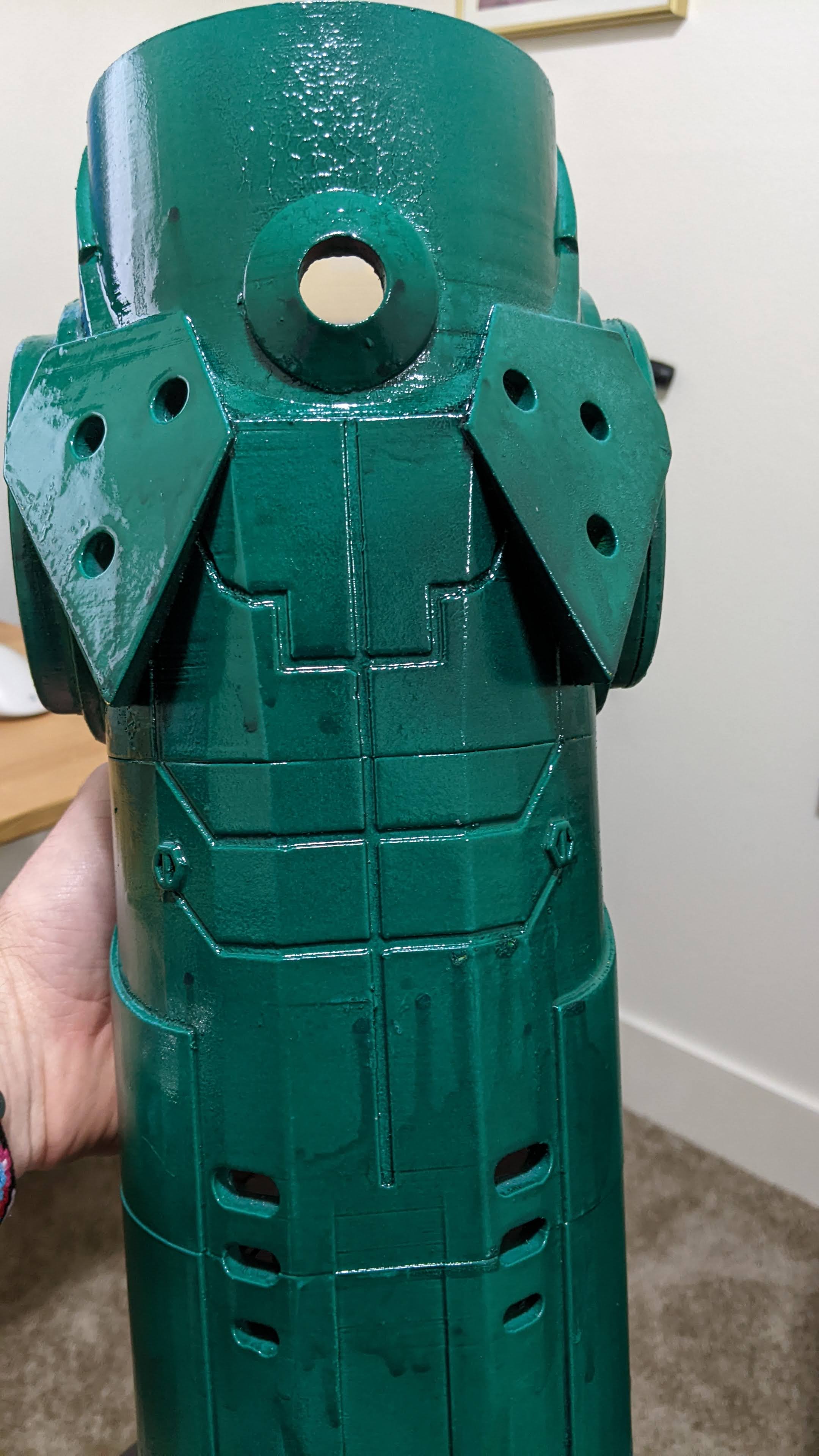
I really think this made a difference. It really does add that extra bit of realism to it all, even if the purpose isn’t obvious … or existant at all.
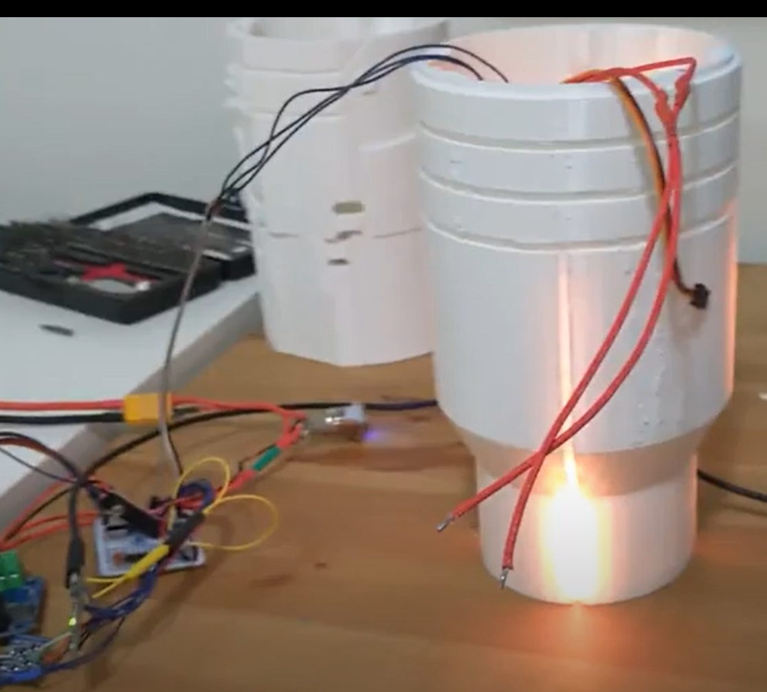
Printing
As you have seen in the pictures above, I had many test prints - especially of the trickier mounting pieces for the flywheel and the servo. Some parts were cut down to test-print only the necessary changes and a bit of support structure, others I printed in entirety again and again (though these tended to be smaller parts). Finally, once everything was locked down, I printed each piece again in white PLA and started screwing it together and mounting all the components inside. The white PLA was so that the LEDs would shine through without the colour being affected - I wanted a nice yellow on the gun, and if the PLA was red then this would absorb some and reflect some internally. White also let the most light through (the elbow piece was printed in red, but it had no LEDs shining through, so this didn’t matter).
The mid-arm pieces were sliced up into several pieces and printed separately; I tried one whole piece, but it messed up 90% of the way through and I lost all that time and filament, so I decided to play it safe after that and print smaller pieces, even though that meant more screw holes and more screws. The elbow piece stayed one solid chunk, as it was harder to divide up, but it printed successfully both times I tried. Here’s some of my duds:
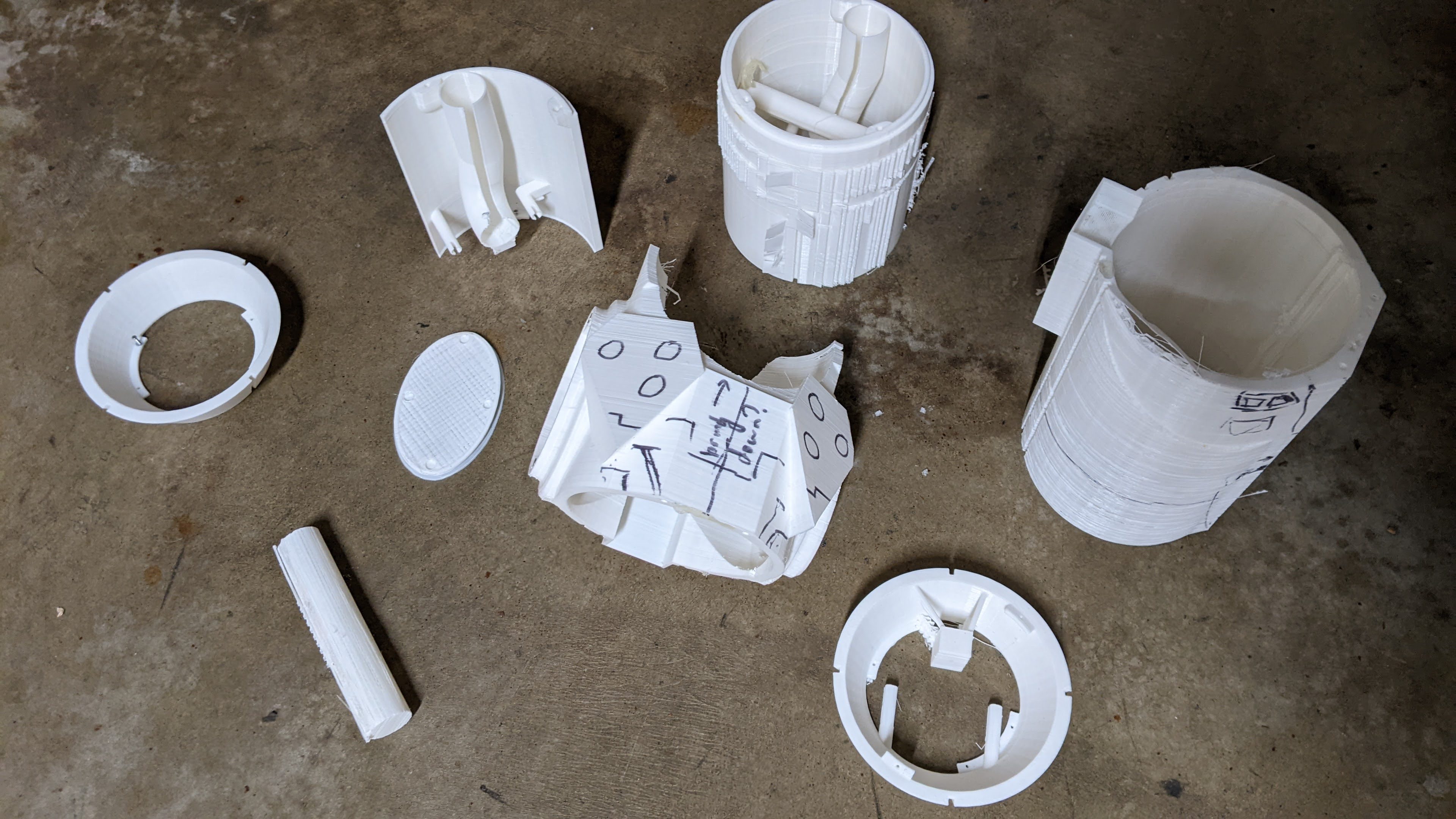
I forgot to count, but probably went through five kilos of PLA to get all this?
Electronics
As I said in Circuit board mounts and access, there’s a bunch of electronics I wanted to have in this:
- a display that fits within the ellipse
- some sort of programmable chip board with IO pins
- a battery
- a motor driver
- LEDs
- buttons
- a servo
There are a few things I know off the bat:
- I need a PWM pin to drive the motor driver - both motors will take the same signal, and just spin in opposite ways due to wiring
- a servo for the trigger would require a single PWM pin as well
- the LEDs are Neopixels, which means I need a single digital pin to drive them
- the display will probably be SPI-controlled, so I need SPI pins on the arduino
- I want at least four buttons, which means four digital input pins.
- I want a hall effect sensor so I know when the cap is off or on, so that’s another digital input
I also wanted to be able to read battery cell voltage (three cells, so three analog input pins). I’ll get to what happened to this later - let’s start with the discussion of the control board.
How many arduinos?
As previously stated, I originally wanted to use a Raspberry pi. Why? Well, for a start I already had a few on hand, plus touch screen displays for them that fit on top. This would mean I wouldn’t need any physical buttons to control the display and I could have a fancy scifi-looking hi tech display. As I also said in the modelling section, I discovered that this would not fit … unfortunately, I discovered this fact after I had already begun the wiring. Alas. Planning ahead is a good idea.
So I found Adafruit’s Feather series, which has a really nice form factor of display, and had an Arduino that contained all the pins I needed - SPI for the display, two PWMs, some digital input and some analog input. So I coded up each part and tested them separately, like any good software developer, and they all worked (with tweaking and cursing):
And then I turned on two components at once - LEDs and servo - and it didn’t work. Why not? Wasn’t sure. Tried display and servo. Tried display and LEDs … nothing. Why?
Well, as I had forgotten, servo control is implemented on the arduino by use of interrupts. The SPI protocol uses precise timing, which can be ruined by .. well, by being interrupted by interrupts. It’s their purpose. Neopixels are also driven with precise timing … less precise than SPI, but can still be ruined by interrupts. Servo control can also be ruined by turning off interrupts.
Alright, how do we reconcile this? Well, Adafruit has a handy blog post about DMA-driven Neopixels - essentially we can use a hardware block on the chip to drive the LEDs, freeing up software for the interrupts for the servo. But that leaves the display unimplemented.
I hummed and hawed about this at length, and eventually settled on .. just using two arduinos. The cost came out to about what I might spend on a bigger chip that could do all three anyway. So I would have one Feather with the dislay, and it would send commands over serial to a secondary arduino that would power the servo, the motors (PWM signals won’t interrupt anything), and the lights. Why won’t serial be messed up by the servo? Well, it will be operating infrequently - I’ll only use serial to tell the secondary arduino any values to use - motor power, light colour, light brightness, and it will set those values internally. Secondly, I used a baud rate (bits per second) of 19200, which is really really slow for the arduinos, so it probably could get interrupted and not even notice.
Now to code up this split design - it’s mostly one way communication, so the screen half just pulls the values saved from EEPROM and renders these, and then the buttons control a cursor on the screen to select the values and increase or decrease them. When the values - cannon power (0-255), cannon brightness (0-255), and optimistically suit LED brightness in case I get round to it (0-255) are changed, whatever changed is sent over serial with a control character to say what changed, and on the other end these are saved into memory to load next time on boot. The rest of the logic is either on LED control, or servo and motor control:
- The LEDs are updated every loop, and run through one of three patterns. There’s a slow pulsing pattern, with a bright spike amidst dull LEDs that travels forwards down the gun, and this is the base state. There’s the ‘charging’ pulse - multiple fast pulses travelling back up the arm - which occurs when the fire button is held down. And finally, there’s the firing pattern, a single big pulse that travels down the gun and ‘out’ the front with the nerf ball, which then transitions back to the base state.
- The firing button on the handgrip controls the servos and motors. These do nothing when the button is not pressed. When the button is held down, the motors spin up, ready to fire. When the button is released, the servo actuates forward, pushing the chambered ball into the flywheels, and then moves back. The code waits a hundred milliseconds to allow the firing to happen before spinning the motors down.
Finally, the display arduino reads from the Hall Effect sensor that is mounted to sit beneath the panel magnet:
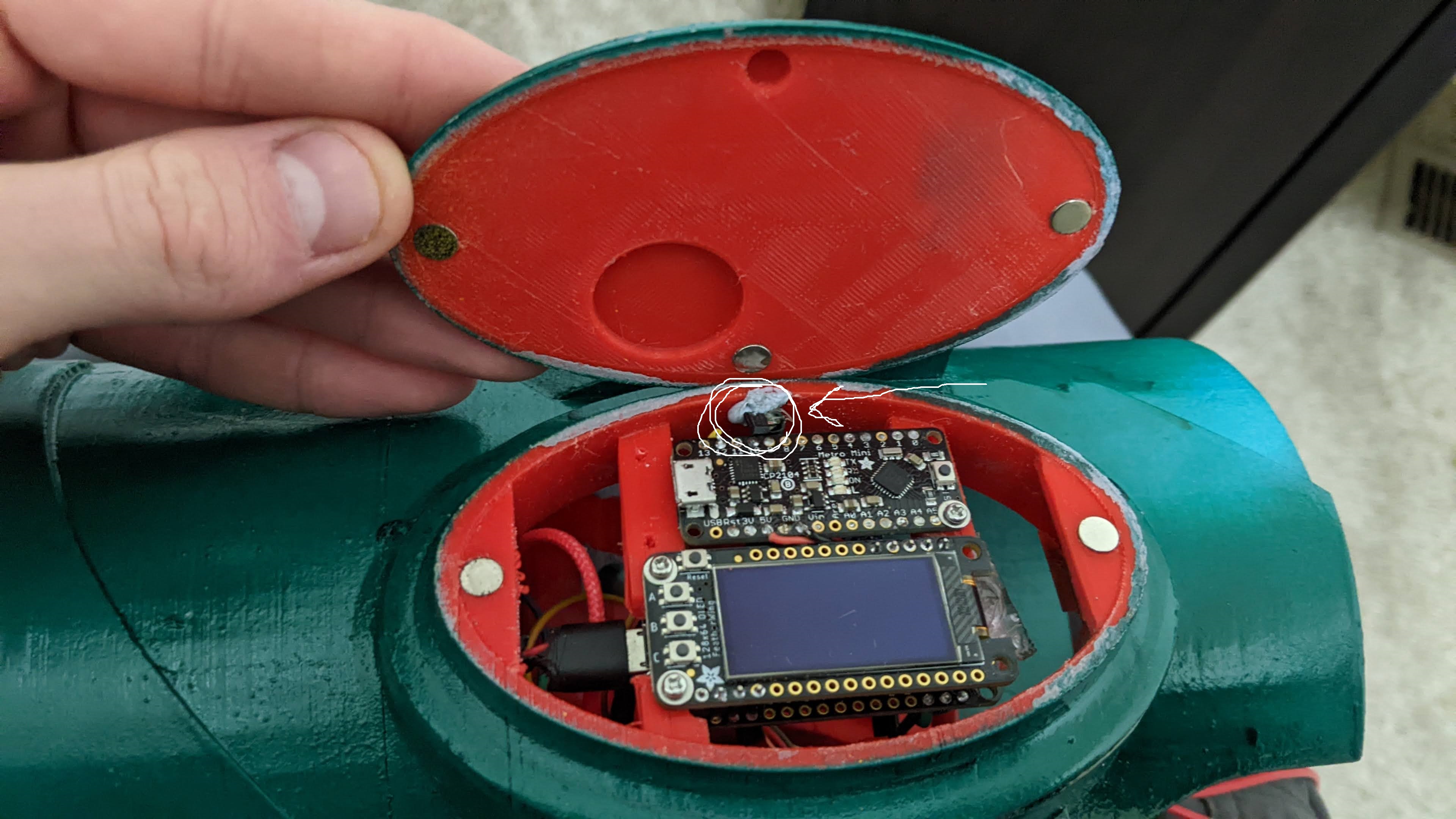
This is a binary signal, normally pulled to digital high but gets pulled low when the hall effect sensor is in the presence of a magnetic field. It’s a simple process to check this every half a second, and if there is a magnetic field present, display nothing on the screen. This allows the display to sleep, which saves power.
All this code can be viewed in the Samus repo on my github.
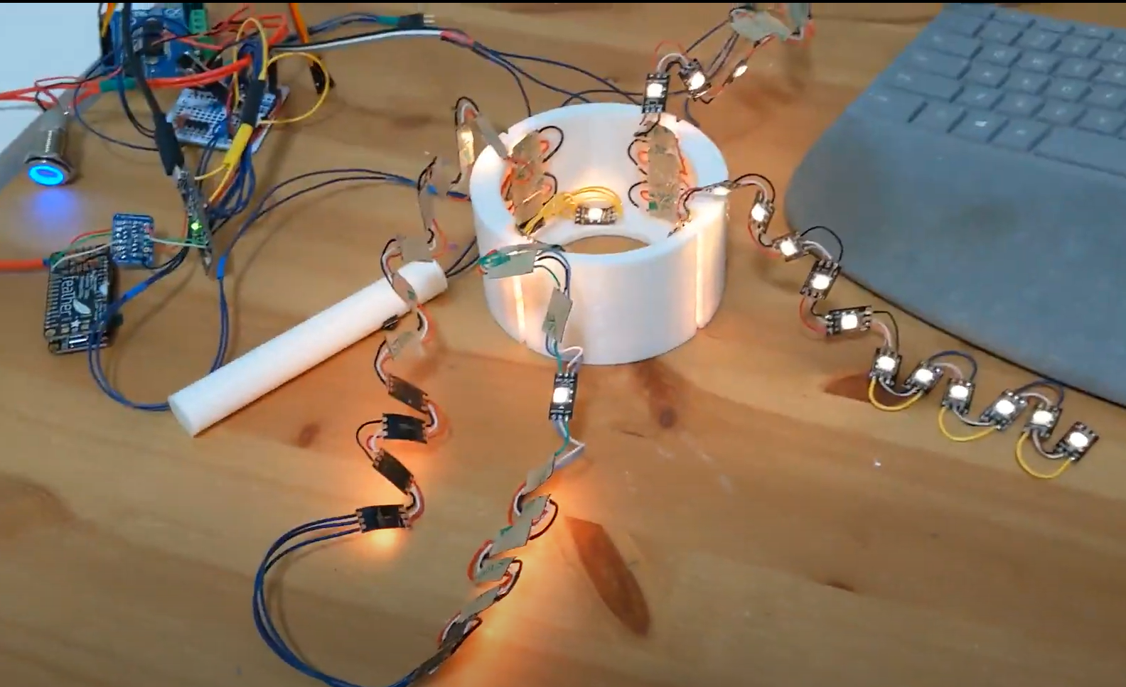
LED mounting
The LEDs were mounted right up against the tube, so they glowed through the white PLA. I had them loosely wired to test and develop the patterns
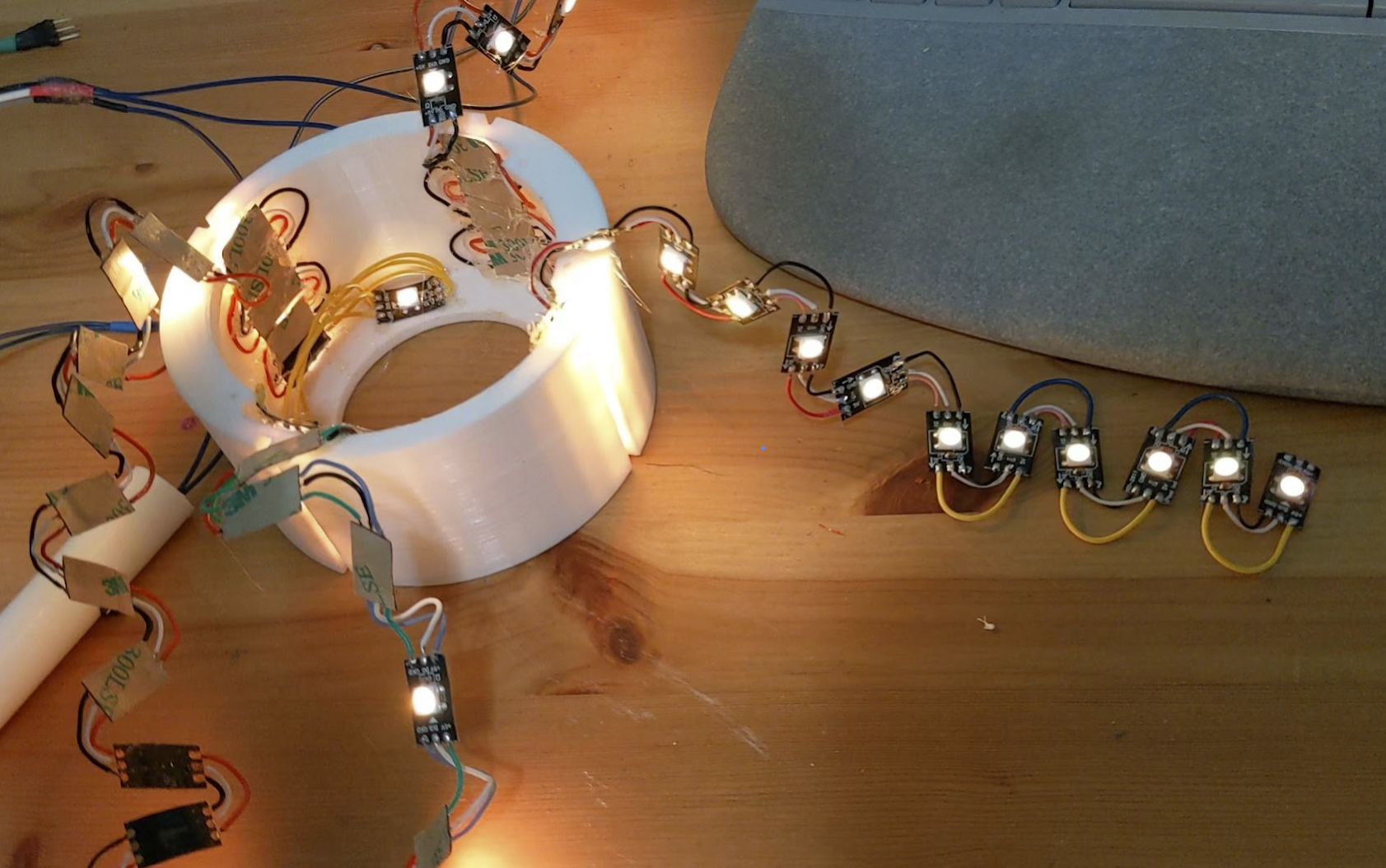
and then later either hot glued them down individually, or mounted them to a printed rigid bar that was glued down so they would stay down:
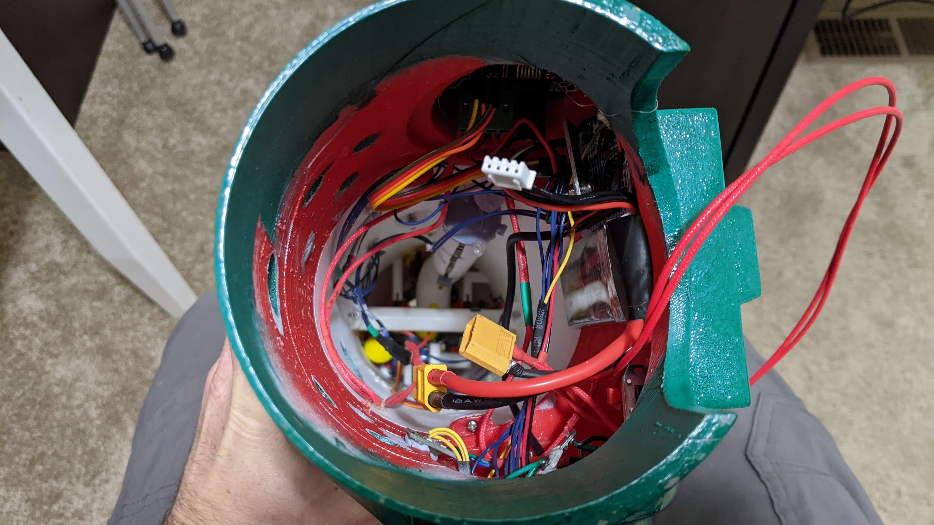
Other circuitry
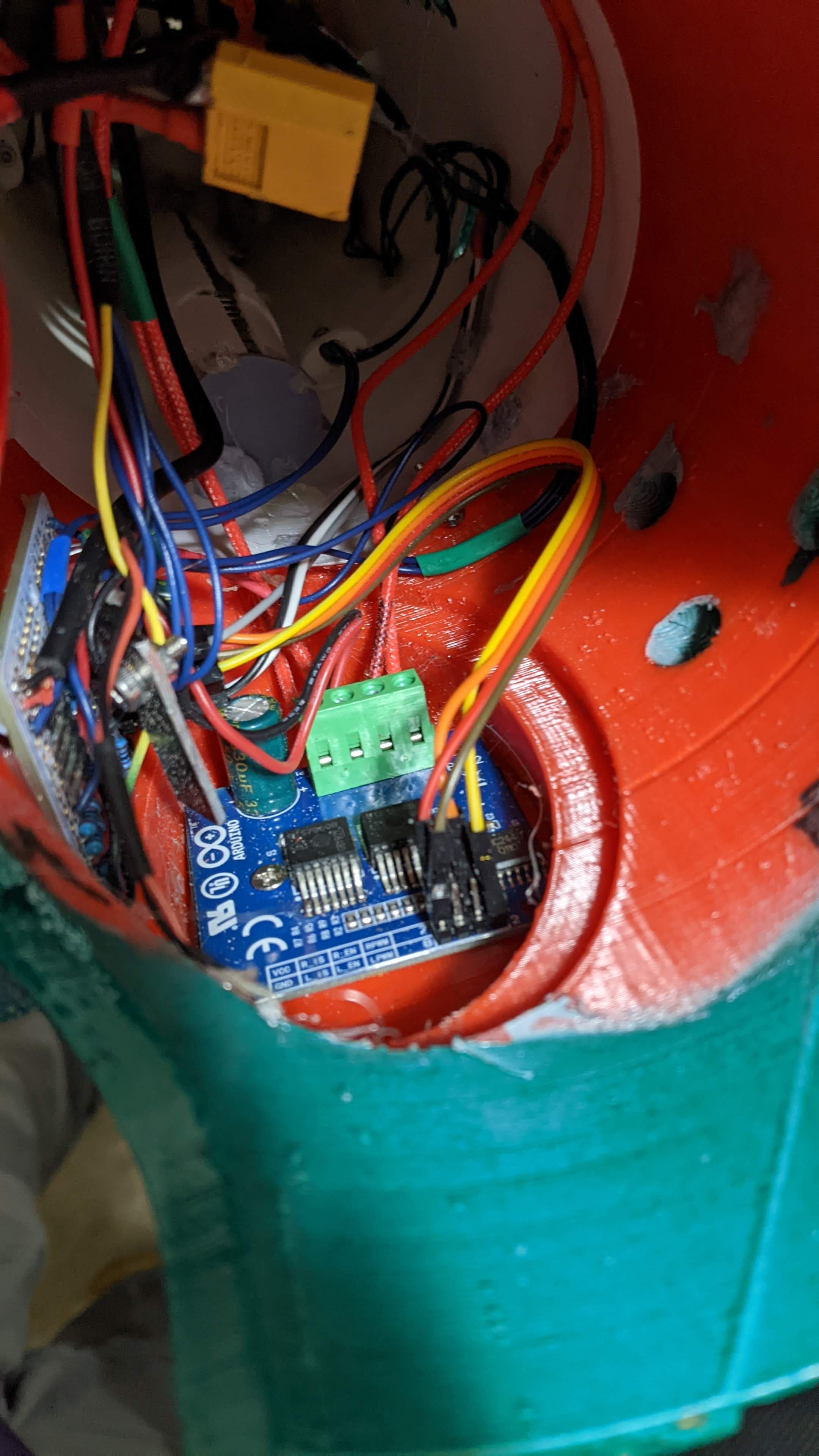
So we have our arduinos, we have our motors, what else do we need? Like I hinted to earlier, I did want to attempt a battery voltage reader, and made a voltage divider from resistors to read the voltage of each cell. Unfortunately this read values that were really off and after some circuit debugging and attempted calibration I abandoned it. So all I needed was a voltage regulator to bring the 12v battery down to 5v to power the lights, arduinos, and servo (it was 1.5 amps, which is easily enough), and then a level switcher to go from the 3.3v feather arduino to the 5v control arduino. This was all awkwardly soldered onto a circuit board that sat below the battery, glued onto the plastic:
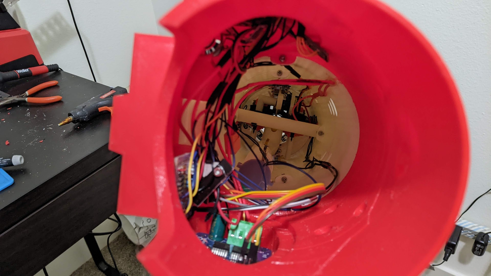
Yes, this is a horrible mishmash of wires, and the circuit went through several designs. I tried to glue a lot of the wires down, but it was hard to get a glue gun in there after the elbow piece. If I did this again, I would design my own circuit board that held everything necessary, and then model wire clips into the sides of the piece to hold eerything out of the way.
Paint
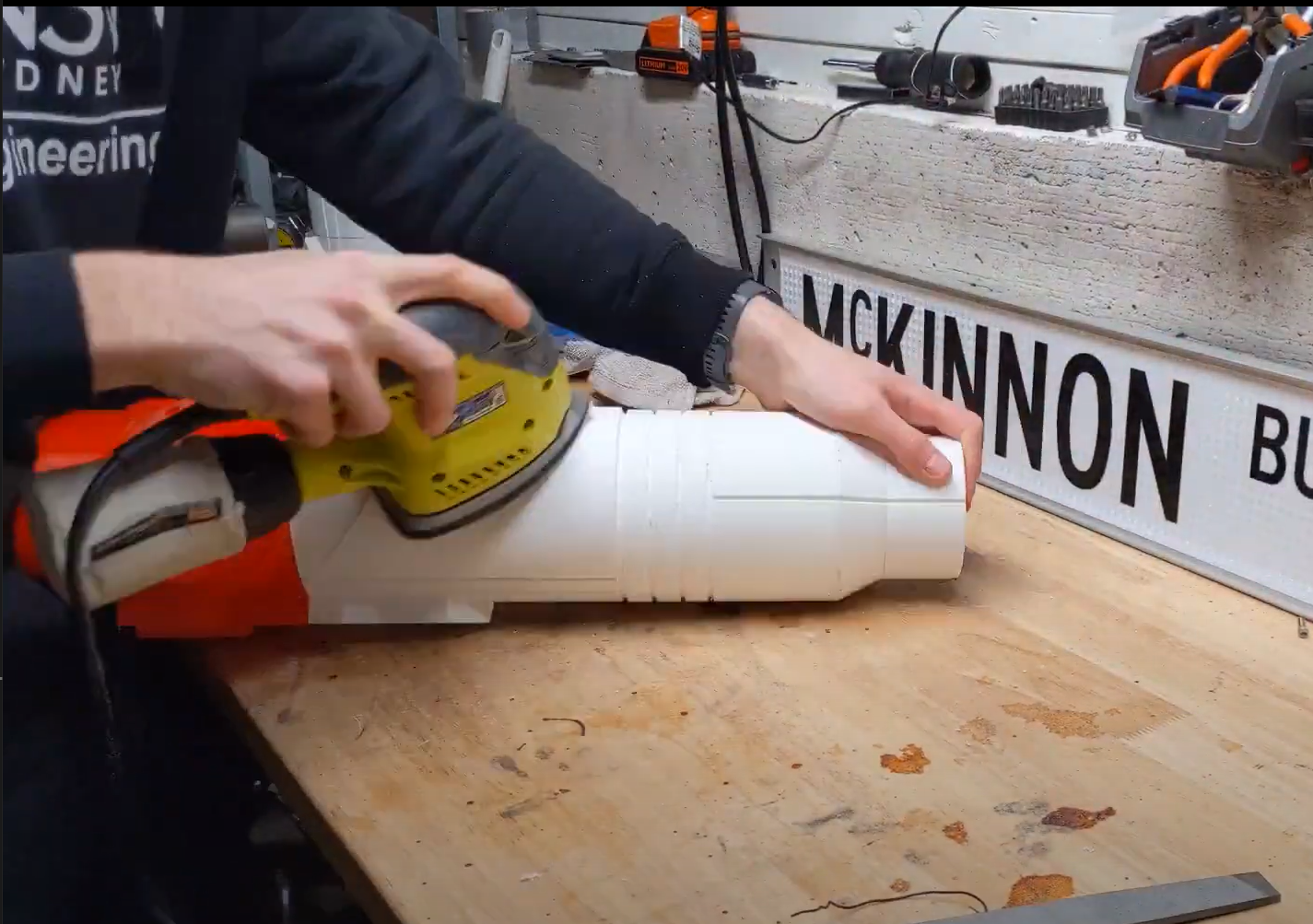
Given that this was 3D printed, I had to sand the surface smooth before painting - otherwise you get print artefacts where you can see the layer lines. First a 60 grit pass, then 120 grit, then 240 grit to polish it off. This was particularly difficult around the little edges, nooks, and crannies, but I got most of it.
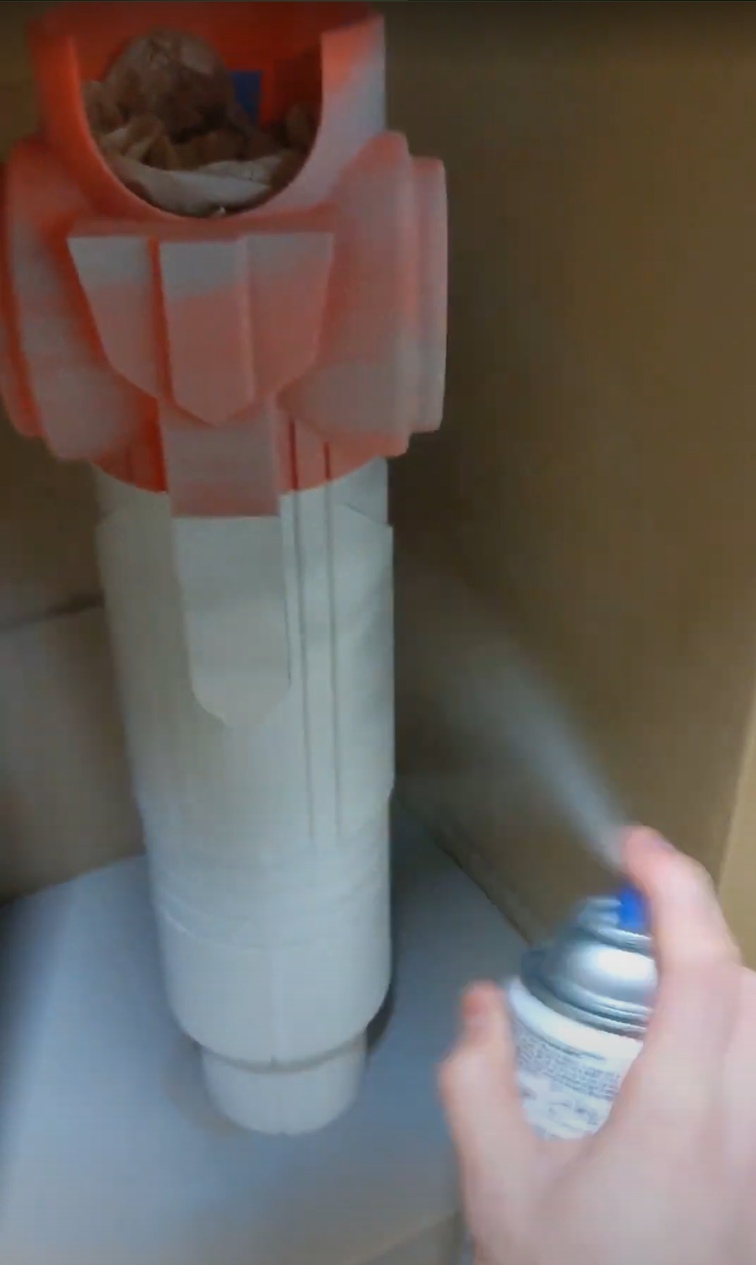
Then came the undercoat layer. I was going off Frankly Built’s painting guide to start - automotive primer, then a base colour layer, then automotive metallic finish. It was difficult finding the right undercoat colour for the metallic green I was using, since these automotive metallic finishes let some undercoat colour through, but not much - eg. for other builds I did gold underneath with a red finish, that mostly looks red but at certain angles you can see the gold combine in with a really nice effect. The primer at least covered most of the sanding imperfections:
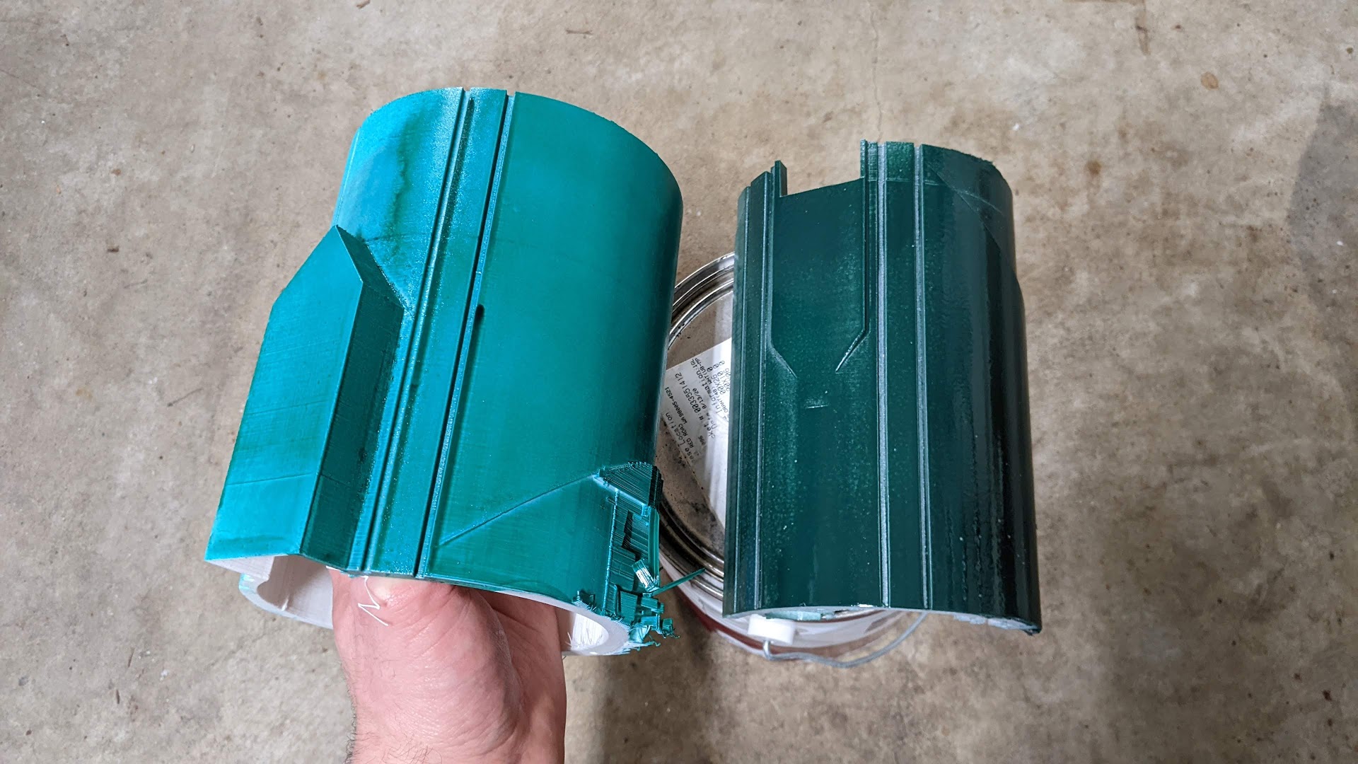
and after that I did an under-undercoat of yellow to get the colour of the inset channels baked in early - then I covered these in masking tape. It took a few cans to get a yellow that looked right, but I settled on Home Depot’s Sunset yellow. Finally, I experimented with a green underlayer, a yellow underlayer, before settling with a base gray, and also used some of my test pieces to find the right green
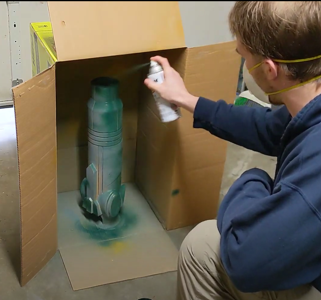
The yellow channels did need some fixing here and there since my masking tape was not perfect. I did this with some yellow paint and a thin paint brush. Unfortunately, I was too rash with the green; you really need to be patient with these paints. It looks like barely anything goes on, but then it starts to run easily.
There’s a few spots where i should have been lighter and just done more layers:
and then some areas where I probably could go back and do another layer. Ah well … at least I can - I could sand off some of the dripped spots, tape everything around, and try again.
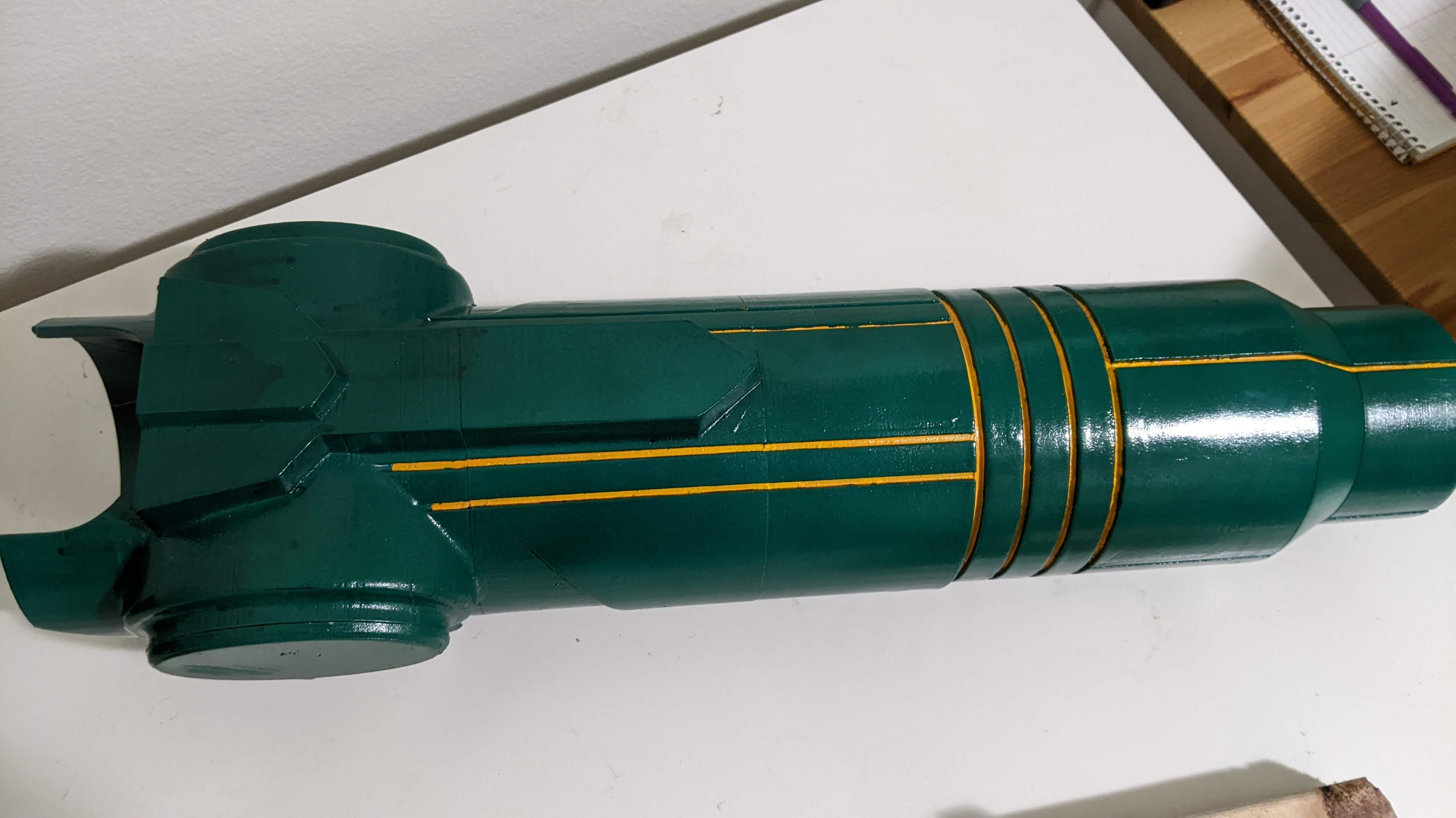
Final product
And here’s how it turned out!
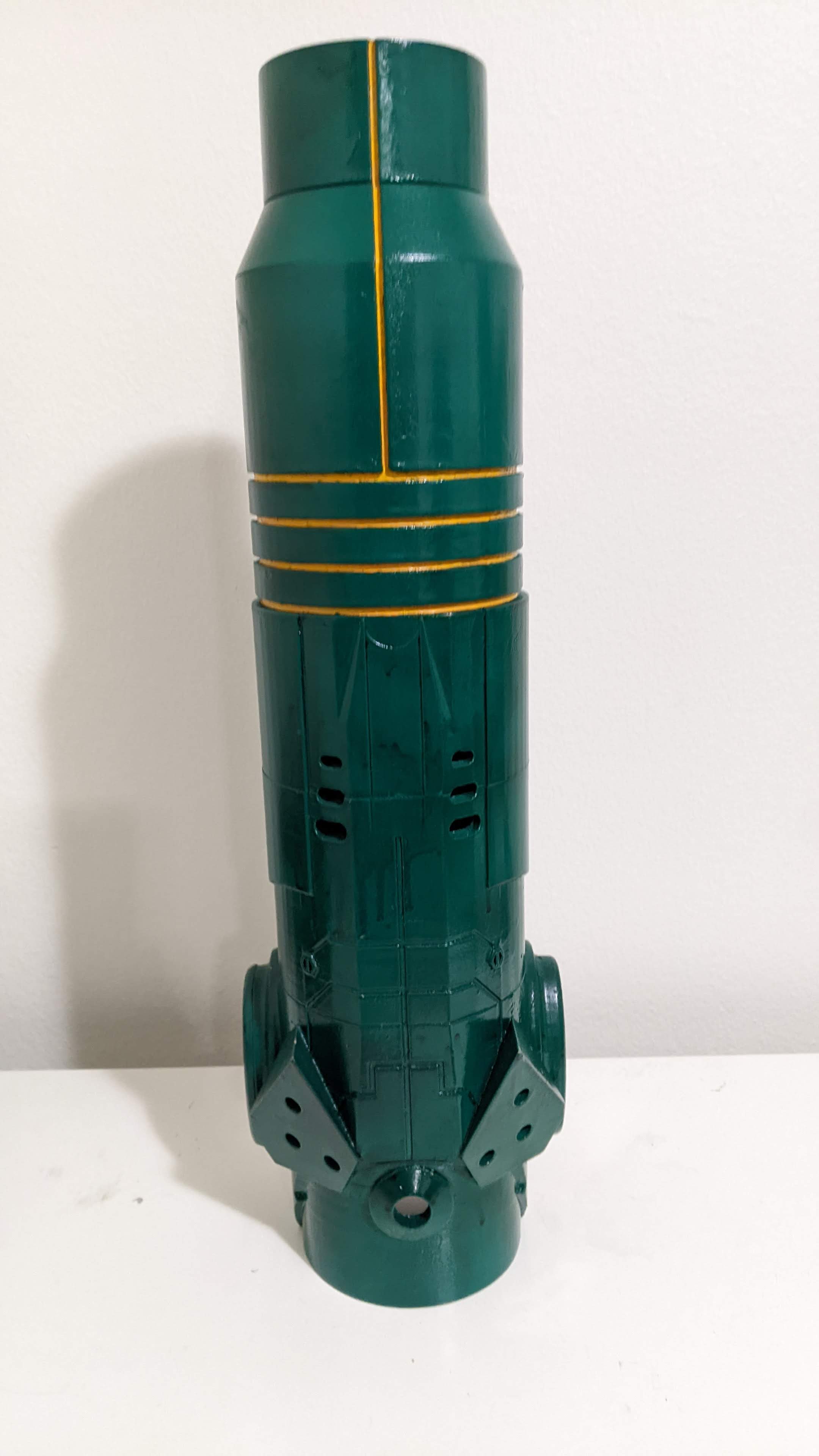

Here’s it lighting up as it fires: you can see the light effects at the gun end.
I’m really proud of this, it turned out so well. The final green and yellow work really well, and it fits on my arm so nicely! My biggest complaints are with the mechanical systems inside:
- the spring end cap can come off easily, and cause the spring to pop out
- sometimes the servo can get stuck, or balls pop out and don’t fire, and it needs adjusting or a good smack
- the wiring gets in the way a lot and makes a lot of things hard
- it’s difficult to upgrade - despite the fact that I can take it apart, the paint has covered the seams nicely, so any changes would ruin this
All that aside, I wore this at a halloween party and it didn’t feel awkward. It’s not too heavy, it’s not too big, and it’s easy to slide off and put to one side.
Let’s compare to a few of the video games:
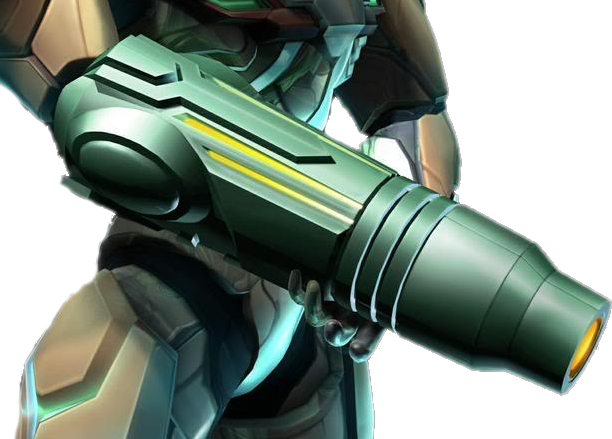
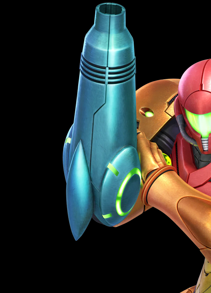
The top is from Metroid Prime, and the bottom from Super Smash Bros - I was certainly aiming for a Prime style, and I think I got close - my colours might be a bit off, and I have small details off, like the greeblies. Mine also cannot open the front hatches for missiles, but that at least was deliberate. It looks about the right length, proportionally.The original model I worked from had a more … dull? Used? Aged? green, which I think works well too. All in all, rather happy with this build.
Models
There’s really only one model available online that I used for this, and I’ve already linked it multiple times but here it is again, explicitly: https://www.thingiverse.com/thing:4546853
Big thanks to LukeRS for modelling it and making it available for free.