Pneumatic muscles
Pneumatic muscles
There have been a couple of projects where I want strong but relatively light actuators. One is a bipedal robot - weight from motors on the legs can help stabilise and reduce inverted pendulum effect, but it also means it adds a torque to the limbs (this is likely negligible. Typical biped legs do not swing out to high angles). Another one involves a large glove that goes over my hand and extends far out, and I want the fingers to actuate. Using electric motors of sufficient strength here means having a number of motors fixed some distance from my hand, when this device is anchored on my arm. That’s a considerable torque, and an uncomfortable one too (unless it’s shoulder day).
Why not electric motors
There are several reasons, but first and foremost let’s say this: electric motors can and will work here, and are probably better in just about every way. They have fine-grained angular and speed control, they’re strong, easily obtainable, easy to run, bidirectional, no hassle with pressure and leaks, and batteries have higher capacity. Having said that, pneumatic muscles offer some of their own advantages - they’re light (a big factor for a wearable project), they have a better strength to weight ratio, they can bend around joints, and are robust to deformations.
The biggest reasons i want to try pneumatic muscles is the strength to weight ratio - specifically, the weight part being low - and also … it’s something new to try! Yes, conventional robotics rarely if ever uses these, but hey, it’ll be a good exercise and make for an interesting project at the very least.
What is a pneumatic muscle?
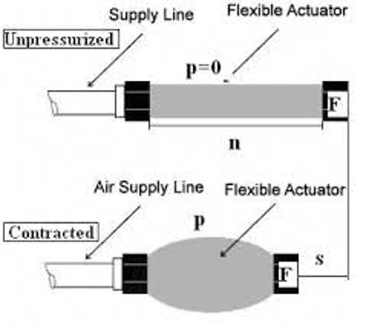
These are sometimes called McKibben muscles. There is a flexible hollow part, the actuator, that will be pressurised. This usually is split into a bladder and some sort of expanding mesh (think a finger trap, or braided cable sleeves) to take the strain. At each end is a rigid cap - these form attachment points to the bodies to be acted upon. Feeding in through one rigid cap is a supply line of air. When the air pressurises the bladder, it expands and so does the mesh - radially. Therefore, it axially - lengthwise - contracts, which pulls the ends together with some force proportional to the pressure. Typically, one end is attached to a frame, and the other to a part that needs moving, or it is attached to an arm around a rotating joint, and this pulls the arm in a rotation.
Think of it like a regular muscle - your bicep is attached to the humerus (upper arm bone) and to the radius/ulna (forearm bones) - and it attaches across a rotating joint (the elbow). When you lift using your bicep, it is contracting, which pulls the two bones together. The forearm rotates towards the upper arm about the elbow with some force.
When these muscles are used to actuate a joint, they are typically paired: one to pull from each direction while the other is slack.
Construction
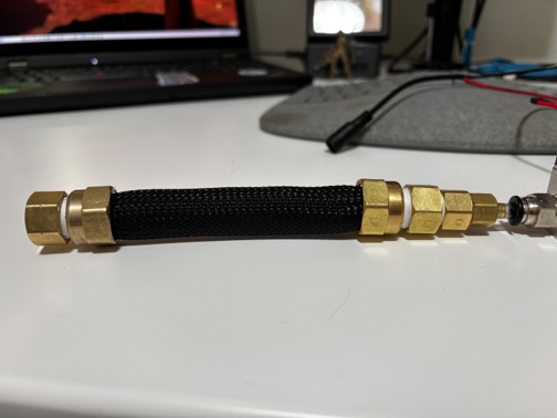
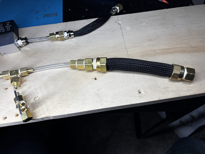
I’ve tried to make the muscles relatively cheaply. The actual muscles themselves are from lengths of braided cable sleeves, and 700cc bicycle inner tubes (i have loads of ones with irreparable holes lying around). The end caps use brass pipe compression fittings from Home Depot - see the list below - and these go to a 5mm hose that can plug into 1/4” press-fit couplings and a 12v solenoid.
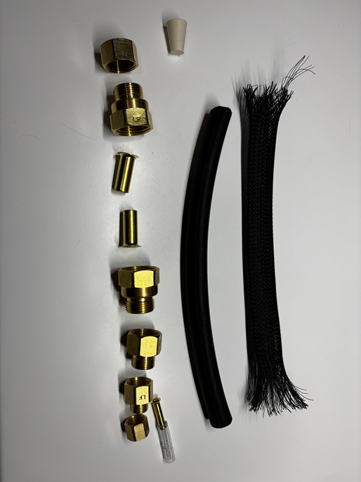
List of end cap parts:
- 1/2” OD to 1/2” ID compression (x2)
- 1/2” ID cap
- 000 cork (cut in half, insert into sleeve beneath cap)
- 1/2” sleeve (x2, should come with coupling)
- 1/2” FEM OD to 3/8 OD adapter (LFA 230)
- 3/8” FEM to 1/4” OD adapter, LFA 157
- 1/4” sleeve
- 1/4” cap with a hole
Feed the bike tyre and mesh through the compression coupling, and insert the sleeve. Push this down into the coupling for a tight fit:
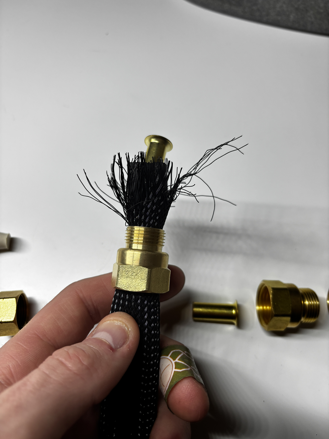
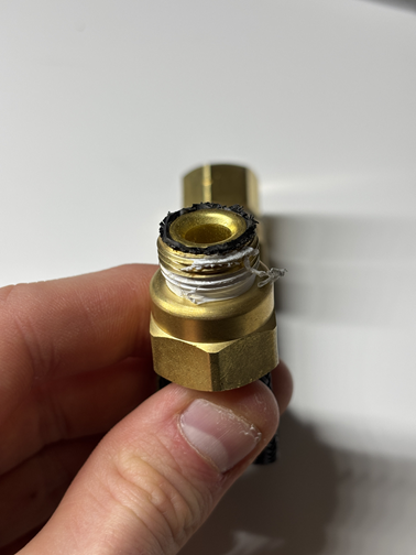
On one end, add the cap. If this does not hold pressure, cut the cork in half, jam the cork in the sleeve, then add the cap back. The cap should press the cork into the sleeve, and maintain pressure. On the other end, add the adapters to convert down to 1/4”. The plastic pipe I use to route between solenoids, the 5mm hose, fits tightly onto this. Push a sleeve through the 1/4” adapter, and jam the 5mm tube onto this. Add the cap and plumber’s tape for a tight fit


Now feed the other end of the tube into a press-fit coupling, this goes into the solenoid … and bam. Air.
Testing
How strong are these? From Wikipedia,
“The retraction strength of the PAM is limited by the sum total strength of individual fibers in the woven shell. The exertion distance is limited by the tightness of the weave; a very loose weave allows greater bulging, which further twists individual fibers in the weave.” My meshes are made from plastic fibers, which together can handle quite a strain. These can also bulge much further than the bladders allow.
Ideally a costume or movable robot would have its own compressed air supply - and a compressor, if not multiple carbon dioxide cannisters. Given that this is just in the testing/early development stages, I’m attaching it to my air compressor with a 150psi tank at however many gallons - basically, a lot of air, but a lot of air that is not particularly mobile. I have been running the system at 50psi, but can crank it to 75.
Now for some numbers. How strong is each muscle? How far does it contract? How much does it weigh?
50 psi appeared to give me the upper limit, in that beyond that pressure, the tube did not noticeably expand any further, just get higher pressure inside.
At 50 psi, the entire muscle contracts 15mm in length. This lifts 4lbs at least, but with 8lbs attached it starts to leak. Yes, I should have more rigorously tested, and got the actual limit. A muscle of length 16cm weighs 114g, using brass components.
As mentioned above, the mesh used can bulge more than this. I made a smaller muscle from a silicone tube, and it barely contracts axially. This is because the tube barely expands under pressure. The bigger muscles I made use a bike tyre, which I know can bulge considerably - why doesn’t it bulge further? Because there is no more room in the mesh - if the mesh bulges more, it contracts axially more and there isn’t room for the tyre that direction. One experiment I’d like to try is remove fibres from the mesh to see if it expands more. The fibres are in groups of four or five, criss-crossing around the perimeter - I’d remove one or two from each group.
Different components
The couplings I’ve used in this muscle have been brass. One 160cm muscle is ~110g, as above (the mesh and tyre do not add much weight, 90% of this is brass). For comparison, one stepper motor is maybe 400g. We’re already saving considerable weight if you think about holding this in a costume on your arm for an hour, or on the end of a robotic limb.
But can we get this lighter? Also, save costs - each brass coupling part is maybe $5-10, and with five-ish parts per muscle, that’s going to add up. What could we use?
Resin
I researched engineering resins for resin 3D-printing - Siraya Blu, Phrozen Rigid series, Anycubic tough - and got Siraya Blu tough (Phrozen Onyx looked a good candidate, but I could only find resin profiles on Phrozen’s printers and most people claimed to use a mixture of Onyx and other resins, with maybe ~30% onyx. This wasn’t helpful).
People have printed threaded parts from these resins - this man printed bolts and nuts in Siraya Blu Tough and tested them for shear strength, tensile strength, practicality (the threads needed to be tapped again), etc. To the best of my knowledge, no one has printed compression fittings with these resins and tried them - or at least, no one has published the results.
Can we print from these parts and get an airtight seal? Will the muscle be just as strong? (well, no - brass will still be better. Will it be strong enough?)
This is still an open question I’m investigating. I’ve tried a couple of resins, like Siraya Blu Tough, but I think my designs were faulty. I was attempting threaded pieces, and these weren’t working well due to poorly-printed threads. I’ve come up with another design that involves two pieces pressed together, and it has more promise. Next post on this topic should have results