ML Business Card
Machine Learning on a Business card
I’ve seen blog posts of business cards that run linux - exhibit A, exhibit B - and as a tinkerer and someone involved in embedded systems, this absolutely tickles me. How cool! Think about what this says of you, immediately!
I really wanted to make a business card like this - specifically, one with a microchip, embedded software, and some fun functionality. But I’m not really an embedded OS person, more of an embedded ML person. Can we run embedded machine learning inference on a business card?
Contents
The Idea
Let’s go over what this would entail. I want a circuit board the size of a business card (about 2” x 3”, or 50mm x 80mm), with my details printed on it. It needs to have a circuit that uses a microchip, and this microchip must run a machine learning algorithm - specifically, a neural network. The neural network should take some input from the user, and give some feedback that it was successful. It also should be powered by USB, for convenience.
I know from the examples above that this is possible. That is, a business-card-sized circuit board with a microchip powered by USB is do-able. The question is: what neural network can we run on such a tiny chip?
Neural networks
Before going further, let’s discuss neural networks. If you already know about them, jump ahead. If you don’t this is not a comprehensive explanation - they’re a dense topic. This is just an overview. A neural network is an algorithm that performs statistical categorisation. Or, in other words, AI. It takes some input like an image or an audio stream, finds some notable pattern within like a collection of pixels that resemble a face, or a collection of frequencies and amplitudes that sound like “hello”, and assign a score to a number of categories. These might be: face, ball, apple, dog. They could be spoken words: hello, goodbye, hey google. A high score for a particular category denotes confidence that “this is it”.
Typically, however, neural networks are computationally intensive - that is, they require a lot of time and mathematics to arrive at an answer. Big powerful processors do this with ease. Tiny microprocessors that fit onto business cards … less so. The neural network needs to be minimal.
A speech recognition neural network sounds like a good idea - this would recognise a set of spoken words, and somehow display which word was spoken to the user. The input here would be a brief snippet of audio. The advantage is that this takes up a lot less memory than, say, an image from a camera. Correspondingly, such neural networks tend to be smaller - especially when they do not detect many words. Microphones can be really small, on the order of millimetres. I can use LEDs to display the result in some way - maybe just recognise numbers spoken, like “one”, “two”, etc, and display the number.
Making my own neural network
Some research uncovered this tutorial. This is a speech recognition neural network model, that is run on an Arduino (read: tiny microprocessor). Perfect! Even better is that the tutorial demonstrates how to train the model with new data, and the training data gives a bigger selection of words to choose from. These include the numbers ‘one’ to ‘nine’. I selected these numbers for the model to detect, ran through the training tutorial, and bam - a small neural network model that recognises a few spoken numbers.
I acquired the Arduino used in the tutorial - the board comes with a microphone on it - uploaded the model and the surrounding software, and ran it. It worked with perhaps ~70% accuracy (70% of the time it correctly identified the number I’d spoken, and displayed it on my computer). This is great! An excellent demonstration that can catch attention. Next step is to design this into a business card.
A prototype
I have the working concept on a working circuit board. So why make something new? Why not just completely reuse this in my own design? It’ll fit within a business card (3” x 2” approx) easily. The circuit board I’m using is about 45mm x 15mm. Arduino even open-sources their hardware, providing all schematics. What’s stopping me?
One main reason: the microchip used, the nRF52840, is a BGA chip. This means that instead of having little legs on the sides to solder the chip down, it has dots underneath. I’ve written about this in more detail elsewhere - suffice to say for here that such microchips are not for novices, and I am still a novice. I need a different microchip.
The RP2040
This is a microchip designed by Raspberry Pi. Important features here include:
- Quad Flat package! This is the opposite of BGA - this has little legs on the side to solder. This is much kinder to a novice.
- nominal 125MHz dual core Cortex M0
- Read: twice as fast as the nRF52840, which we know runs the software. So this is easily fast enough.
- 520Kb RAM
- The neural network is 46kB, the rest of the software ~200kB, so this is easily enough
- Programming it is really easy
- well documented and supported
Downsides:
- The software I have that I know works was written for the nRF microchip. I can rewrite it for the RP2040, it just takes time.
The upsides were enough to overcome the (minimal) downside. I acquired a dev board for this chip, ported the software, and got the tutorial I had before running. I also added extra software to display the numerical result on some LEDs wired to the board.
Software differences and issues
The software for the RP2040 is largely the same as for the Arduino nRF board. It was easy to add in the extra control I wanted: there was a spot for “oh we have detected a word that we want with sufficient confidence”. However, this was not without difficulties.
As far as I was aware, I set the two microphones up the same (16kHz sample rate, 2-byte samples), but the audio I got was giving different results. Namely, on the nRF I would get reasonable results (ie. it said “you detected a five” when I spoke “five” and so on, about 70% of the time), but on the RP2040, it would detect ‘eight’ most of the time and otherwise … nothing. Why?
There’s a long story in here where I dug thorugh every part of the program. A major red herring was that the nRF chip has some hardware-optimised Neural Network operations that the RP2040 does not, so it could well have been computing differently. It should not have been, this should get the same numbers, but ‘should’ is a dangerous word in computing.
It turns out this was not the cause. The cause was the audio sampling. The nRF ostensibly sampled at 16kHz, but provided 256 samples over 144ms - this is approximately 2kHz. The documentation claims that there are hardware filters and other stuff happening on the audio, so this makes some sense. The PDM library I used for the RP2040 theoretically does the same filters, but given that the nRF hardware stuff is proprietary, it’s likely there’s more they aren’t saying.
So the RP2040 was giving me 256 samples over 16ms (which is precisely 16kHz), as expected. Probably this was too noisy a signal, or too short a signal, or … the neural network just expected more preprocessing on the signal than this had had, and that was giving me failures. I overcame this by increasing the number of samples and therefore the time window we got audio snippets over, to 1024. This worked in that it produced a good result … if you speak slowly. Think of how people in shows speak when the other character has a poor grasp of the language - it’s like that. “Ththththrrrreeeee”, dragging each sound out. It works? (shrug)
Designing the circuit
Like Arduino, Raspberry Pi open sourced the dev board I used, the Raspberry Pi Pico. It’s relatively simple - power regulation, flash memory, the chip itself, an LED, a crystal, some passive components, and all other pins broken out to the edges of the physical board.
What I need here is: power regulation, flash memory, the chip itself, more LEDs, a crystal, and the PDM microphone. This should not be too difficult, especially given that the documentation with the chip provides a sample circuit, including the KiCAD files.
KiCAD
KiCAD is a program for electronic circuit design. There are two main interfaces I care about: schematic, and the PCB.
The schematic lays out the theory of the circuit: which components are used, what are their connections. So I add the chip, power, flash memory, leds, etc and connect as needed. Here’s an example:
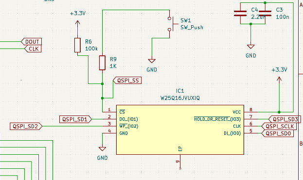
Here we see the flash memory for the RP2040. I’d copied this straight from the examples Raspberry Pi provided. Several pins are pulled high or low (3.3v or ground respectively), some have decoupling capacitors, one is connected to a switch - this gets pulled low to program the device. Several are connected to labels that are used elsewhere. The full schematic is here.
Then there is the PCB design. This is the physical layout that will be on the actual board. First, the outline of the board is created from the edge.cuts layer:
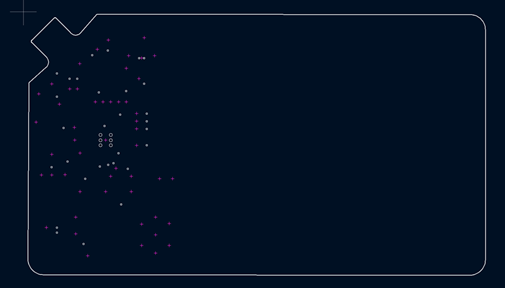
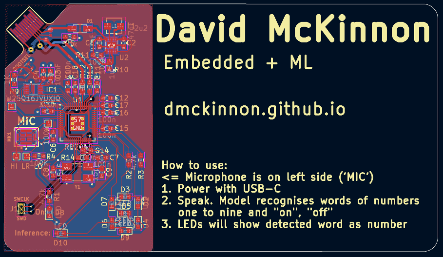
This has the dimensions of a business card (~80mm x ~50mm), but one corner is cut out for a USB-C insert. Most of the rest of the board is unused by the circuit and I just filled it with business card text: name, email, description, and instructions on card usage. Why is the circuit crammed into one side and not more spread out? Well, firstly spread out would make the text arrangement harder - I don’t want components and text mixed, for readability. Secondly, short tracks benefit small circuits - or rather, long tracks are detrimental. Extra resistance, etc. So, let’s cram it tiny.
The board is 0.8mm thick, which is the thickness inside a USB “male” connector. Male is in quotes because technically the “female” half of USB has a “male” part in it too (is it non binary?). This board acts as the outtie bit in the female connector. Let’s look at the USB-C part:
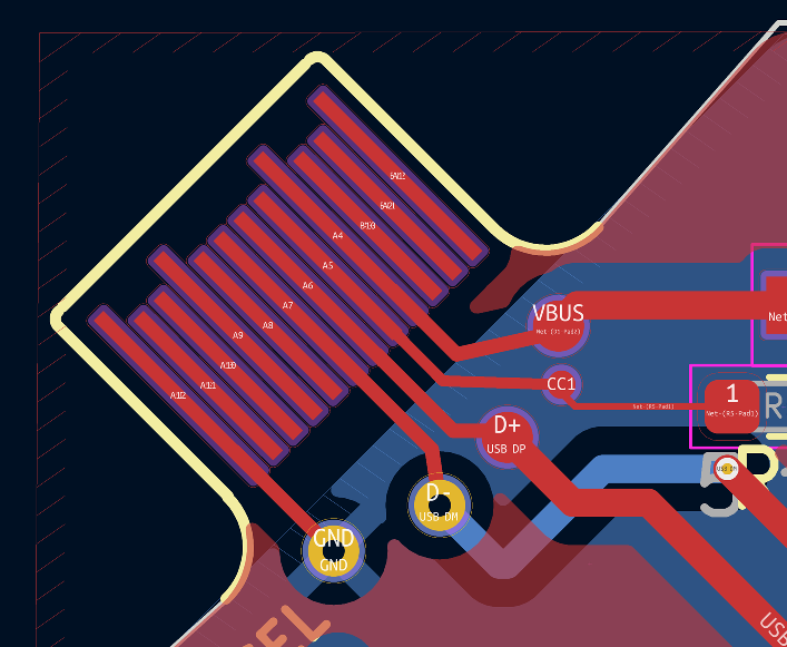
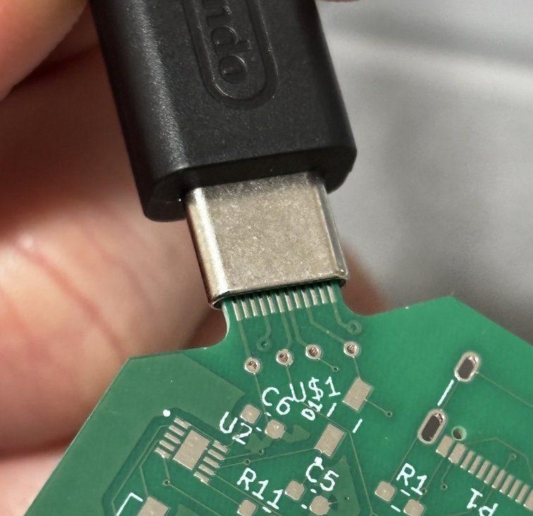
There are tracks only on one side since the circuit only need be one side. The tracks used are the ones necessary for USB 2.0 mode, as I only need this for data transfer - to program and debug - and thereafter for power. Thankfully, this worked first go. As a backup, the first circuit had a place for an on-board USB connector, but this went unused for later versions (See below)
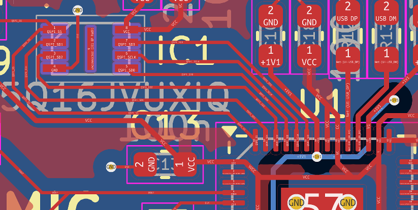
Next, we arrange the components. The RP2040 is biggest and central, but the tracks around it should be sensibly arranged. For example, the flash chip uses the pins on the top side of the RP2040 - so let’s place it there:
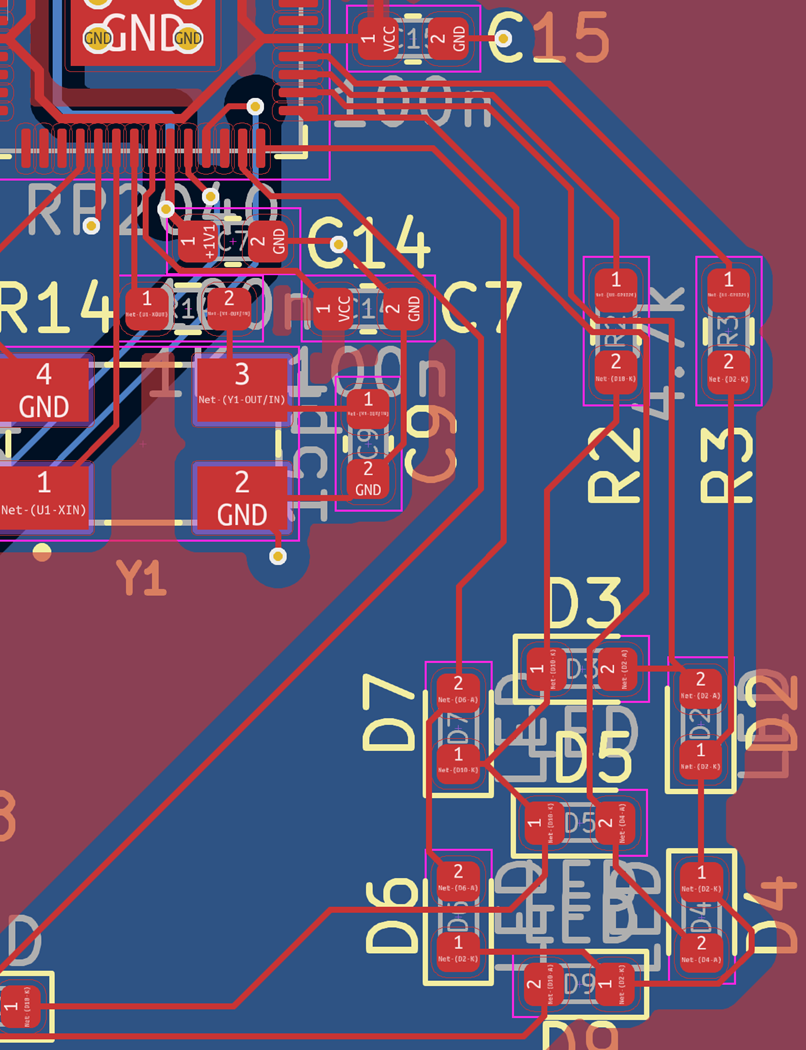
I made sure the LEDs used pins on the right side, as the crystal used some of the bottom pins:
The pins for the PDM microphone are on the left:
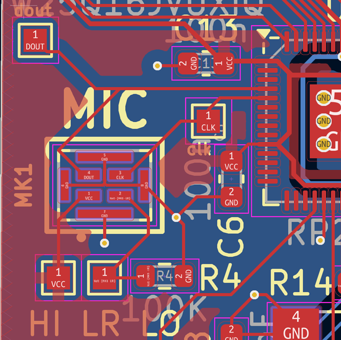
and around it are decoupling capacitors.
The LEDs are arranged in a 7-segment display configuration:
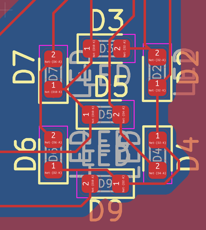
Originally I had 4, and would display the result in binary. Someone pointed out that 7-segment and decimal was just … clearer. Less ambiguous and confusing. Fair point, and I do have GPIO pins to spare.
This entire circuit and process went through several iterations, as I made mistakes, forgot connections, redesigned, and so on. This is the final design:
Mistakes along the way
The circuit design had three distinct iterations, due to several mistakes.
The first design I connected the Chip Select pin for the Flash Memory incorrectly - it was always pulled high, so I couldn’t use the button to select “write your program to memory” mode. Whoops.
Second iteration corrected this, but kept another mistake that had been in the first design and I just hadn’t spotted it due to the first error. There are several pins on the RP2040 that require 1.1v power for the CPU. There is another pin that supplies this power, and these pins all need to be externally connected. I had misread the reference design I was using, and missed these connections. This meant, essentially, that the CPU was not powered. No power means no speech recognition.
So even when copying from a reference design mistakes can be made. Both these points were highlighted in the documentation too, and the biggest mistake was probably not readin ghtis in entirety first. If there is good documentation … read the documentation.
Manufacturing the circuit
PCBWay manufactured the board for $15 for ten boards, using USPS shipping (~5 for the boards, ~9 for shipping). Mouser provided the parts, at varying costs. Unfortunately this is quite an expensive board, for a couple of reasons:
- the flash chip isn’t cheap
- the buckboost converter for power regulation isn’t cheap
- this could absolutely have been made cheaper, I could use a linear regulator. They are less efficient, but this is not battery powered so that does not matter.
- the microphone is not cheap (over a dollar per mic!)
All in all, the cost is perhaps ~$12 a board? Pricey, when compared to some of the Linux business cards I saw online (one was at $3 a board). Ah well, I’ll design the next one with price in mind. If one of these got me a job, $12 is well worth it.
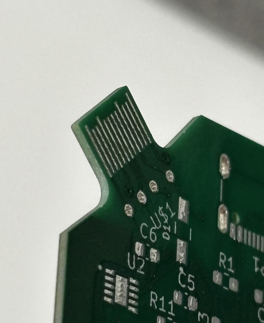
I soldered the boards myself - Josh Elsdon is a friend and has a SMD soldering setup. A controllable-pressure heat gun, and a soldering iron with a really fine tip, plus solder paste and flux.
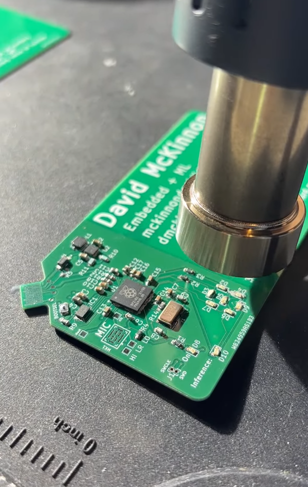
Definitely the hardest thing I have soldered, but it got easier with practice. See this for my difficulties with the microphone.
Final Product
And yet I got it working!
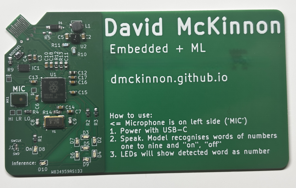
Can’t exactly have a video on this page, but it’s largely working. See the software section for the details here - the tl;dr is that it detects the expected audio when you speak slowly and clearly enunciate and drag out each phoneme. Not a great experience? At this stage .. I could work on this a whole lot longer, I could dig into the signal processing, I could maybe train a new neural network with different preprocessing expectations, oooorrrr ….
I could say this is sufficient, and meets my initial goal. I’m happy with this check point. Maybe I’ll revisit this one day?
For those interested in the code, it can be found on my github: (https://github.com/dmckinnon/mlcard)[https://github.com/dmckinnon/mlcard]
Reactions
I have shown this to some of my peers in the AI industry - some electrical engineers, some software engineers. Reactions range from confusion - “hang on, what’s it do?” (and given that I have to explain, it rarely goes well) - to “wow!” and they think it’s so cool and want one themselves. This is basically the reaction I want. If I hand this to a hiring manager, I want it to capture their attention in a way that makes them remember me and associate me with a really cool hobby project.
Things I would change
An idea I had - after I’d had the final boards made - was that if this truly was a business card I would give to someone else, with no expectation of it being returned, then a useful addition would be to break out the remaining pins to solderable header plates on the edge of the card. Why? So that someone could program this themselves and use it as a Raspberry Pi Pico, albeit with the microphone attached. Then, whenever they use this dev board, they are reminded of me. Ah well, next iteration.
The second main improvement I would do is cost-related: instead of the buck-boost converter from 5v to 3.3v, which involves the inductor and the diode, I would simply use the recommendation from the RP2040 hardware reference doc: a linear regulator. Simpler, cheaper, fewer parts. Less efficient, sure, but this is not my concern since a) I’m running off USB power, and b) this is rarely running anyway. Again, something to change for next time.